This post is a follow up of the post Shading and Light grid, presenting the fabrication of model of the light grid system. The images are extracted from a paper presented at the Design Modelling Symposium Berlin 2013. The paper was written by C. Jiang, J. Wang, P. Bompas, H. Pottmann, and J. Wallner. Freeform shading and lighting systems from planar quads. In C. Gengnagel, A. Kilian, J. Nembrini, and F. Scheurer, editors, Rethinking Prototyping – Proc. Design Modelling Symposium Berlin 2013, pages 335-346. epubli GmbH, Berlin, 2013, ISBN 978-3-8442-6845-4.
All the models were made by C. Jiang and J. Wang.
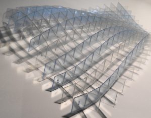
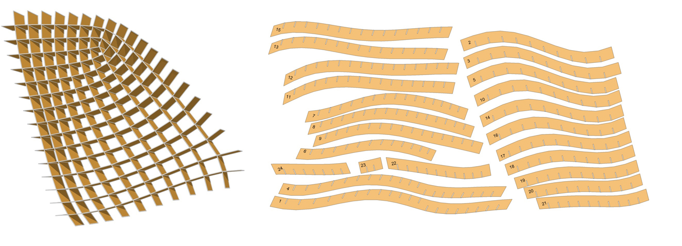
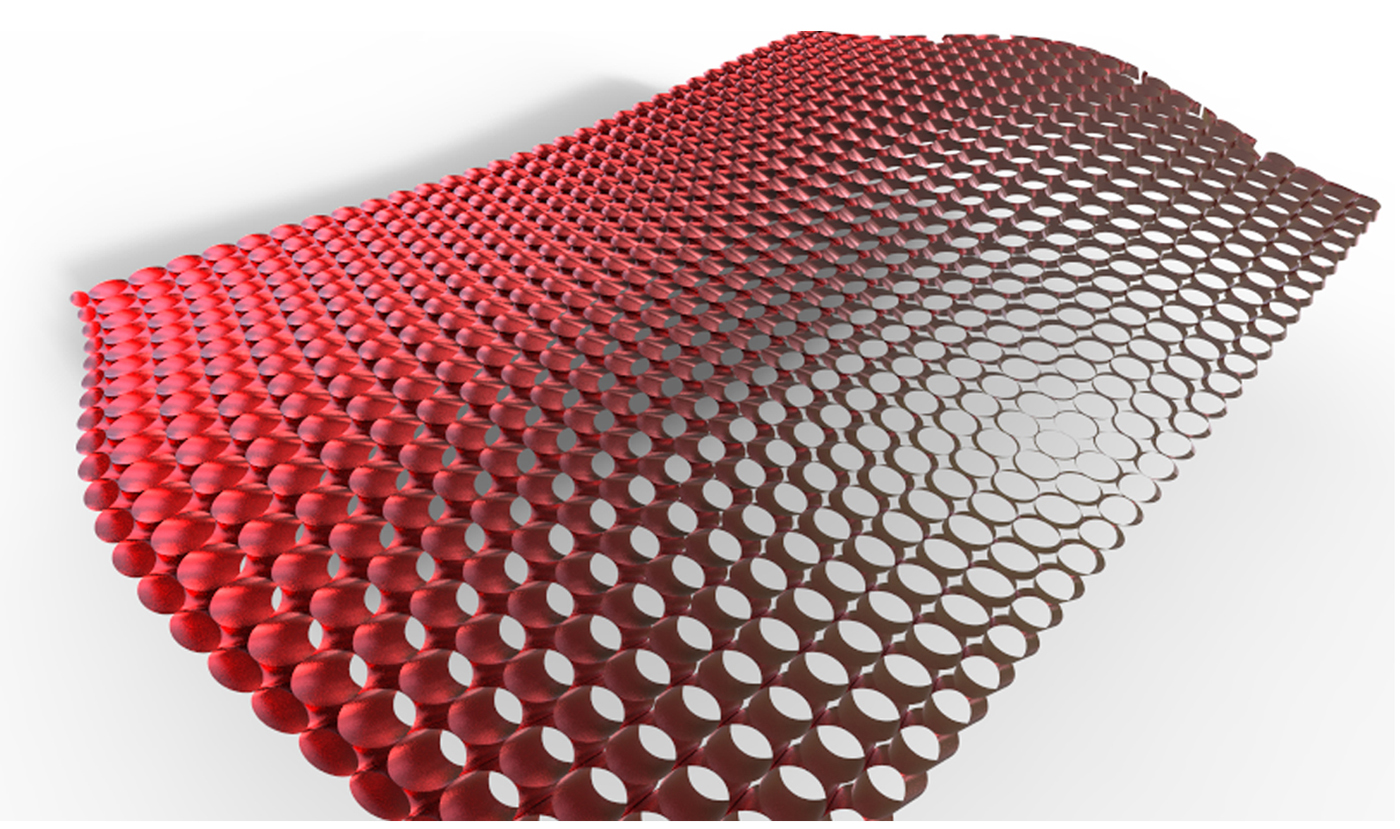
The fabrications of these meshes are not easy, but possible. It is very similar to the stiffening system used for the boat hull. All the pieces are CNC cut, assembled by welding. The difficulty reside in the singularity points where there are a convergence of strips, with certain shape these are unavoidable and constitute not only something that is not always desire but a complicate area to fabricate.
The mesh doesn’t behave as shell structure since it doesn’t have an actual membrane in plane, it is just the stiffening system. Somehow some in plan stiffening need to be provided.
The mesh doesn’t behave as shell structure since it doesn’t have an actual membrane in plane; it is just the stiffening system. Somehow some in plan stiffening will need to be provided.
The facets are optimized for Shade, in many case their orientations are not optimum to care the load, dead load as well as in plan (of the original surface) load for wind. We are thinking of several possible remedy , the first one would be to evaluated the behavior of each mesh, at the worse they need a support structure and will be a filling element, which will be stiffen as necessary. Second ly, it is possible to create a conjugate network of thin or beam that will be oriented in an optimal fashion to carry dead load.
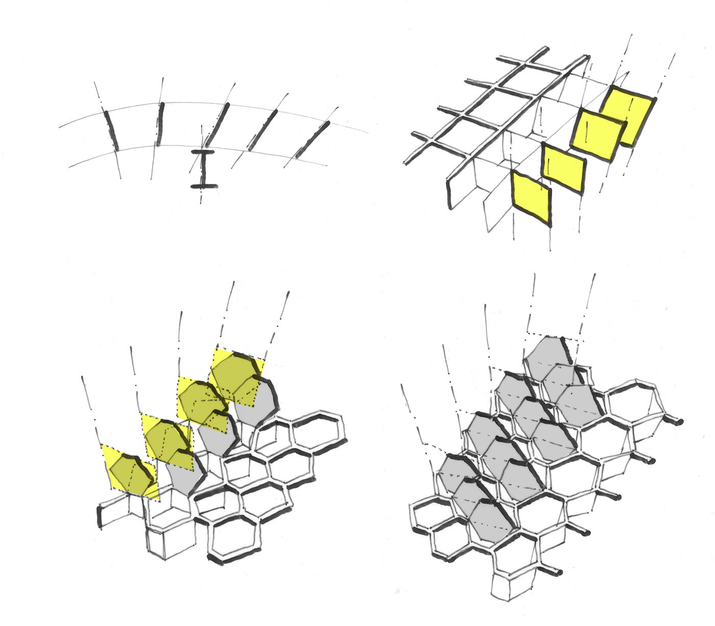
In the following paragraphs, two possible fabrication alternative of the mesh are presented. The first one is inspired from an early experiment presented on this website called constellations.
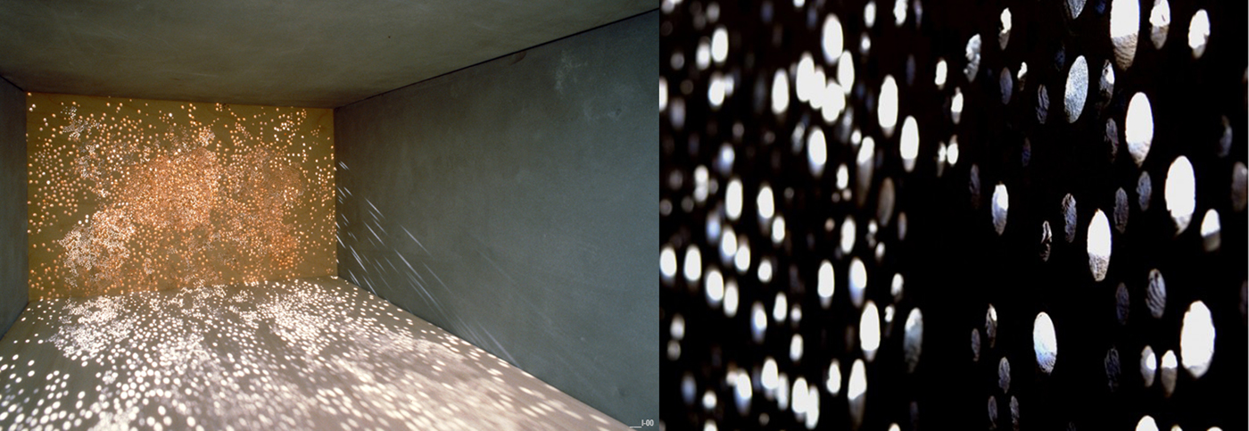
The idea was to create many holes in different angles which would be active at different moment of the day according to the sun angle. Here the idea is exactly the opposite the holes are oriented close to the line of congruence found at each nods, to actually block the sun.
In the image above, the quad mesh are extruded into tube according to the congruence lines. To minimize the number of type of holes, we propose to make some family of holes or tube with would be oriented to the line of congruence.
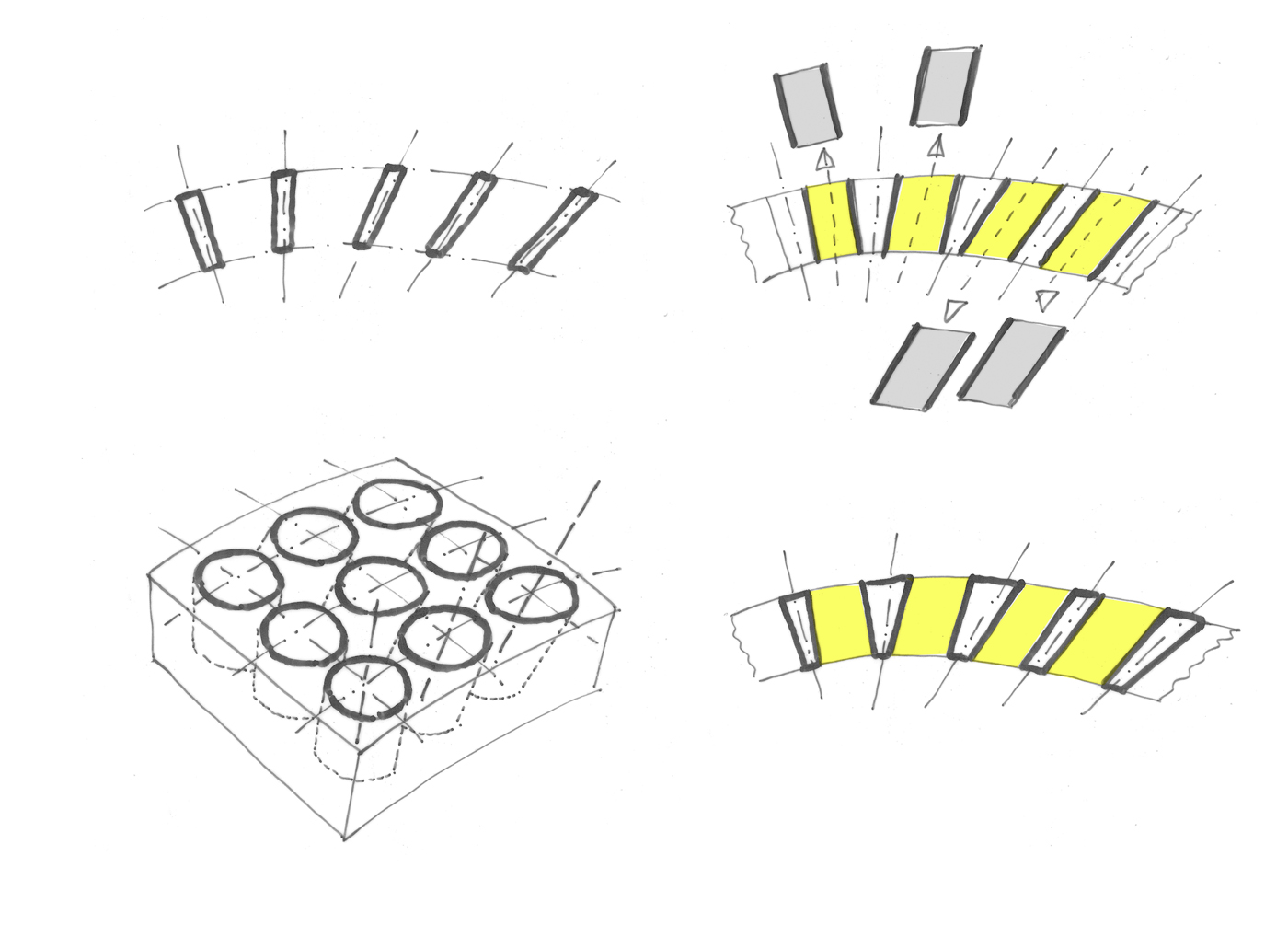
These tubes are use as a filler for a concrete frame work, we use regular tube not conical to be sure to able to remove the tube once the concrete is cured. The concrete grid would be a bit irregular due to the approximation with regular tube instead of conical. This idea still remains to be tested.
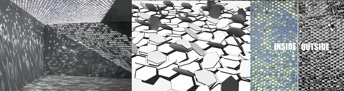
The second one is also inspired for an early work, called the Light shredder, and from a very nice project built Chris Kabel which as similar approach.
Here the idea is to orient some reflectors according to the congruence direction to reflect light below. These reflectors would be laser cut and applied onto a grid, some adaptation would be necessary but one could anticipated some quite interesting light play.