Shading in buildings has become an unavoidable topic. On one side, light is needed and looked for and buildings tend to be as open as possible, meaning as transparent. On the other side using too much glass implies some potential heat gains that are too costly to deal with in the summer, whereas in the winter they are welcome…
This is what happens in moderate and continental climate, shading is a more stringent constrain in drier climate.
Glazing has its limits, some extra-ordinary improvement in coating technology have been done, and more are coming, but until an infra-red selective coating is getting out of the lab and become a commercial product, designer are left with glass product that end up being very reflective and dark, if you are looking for g factor around 0.1- 0.15 which is more and more a requirement. The choice are limited, in short, either reducing the amount of glass, like it or not, or finding some hard occultation systems, blinds, micro blinds, curtains, mesh, active or not, outside the glass or integrated into the IGU. Here is a alternate approach which is at a research stage, so there are quite some more work still to be done, but it might be of inspiration.
This paper was published in Computer Graphics Forum 32/5 (2013), 53-62, Proc. Symposium Geometry Processing. It was written by Jun Wang, Caigui Jiang, Philippe Bompas, Johannes wallner, Helmut Pottman … My participation was limited to the application part of the paper. For more information and more technical and geometrical aspect: see the full version of paper
Scientific papers follow strict rules and logic, more over for this kind of paper led by mathematicians; this doesn’t let much room to develop about the architectural potential. This is not a criticism just a simple fact, so I will try to emphasis hereby on the architectural potentials, I find with these findings.
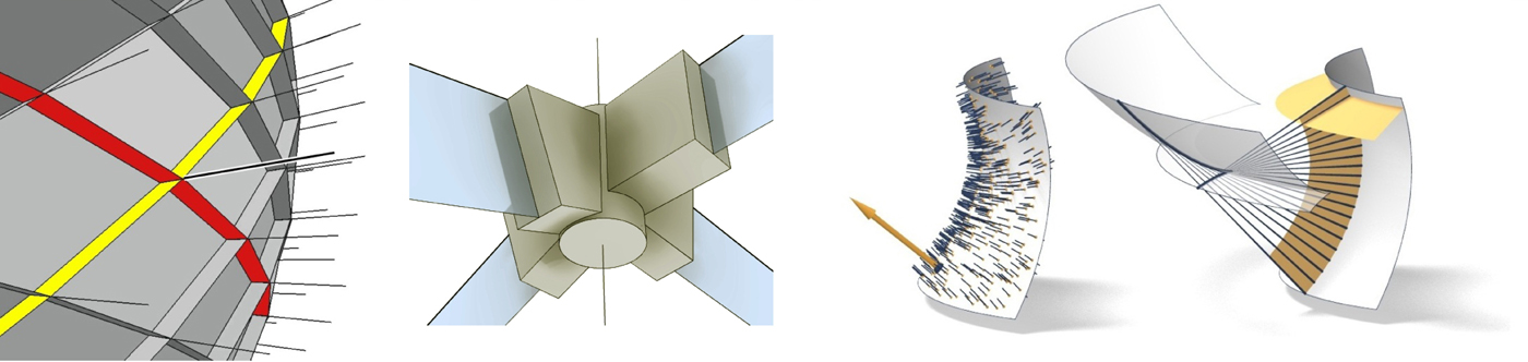
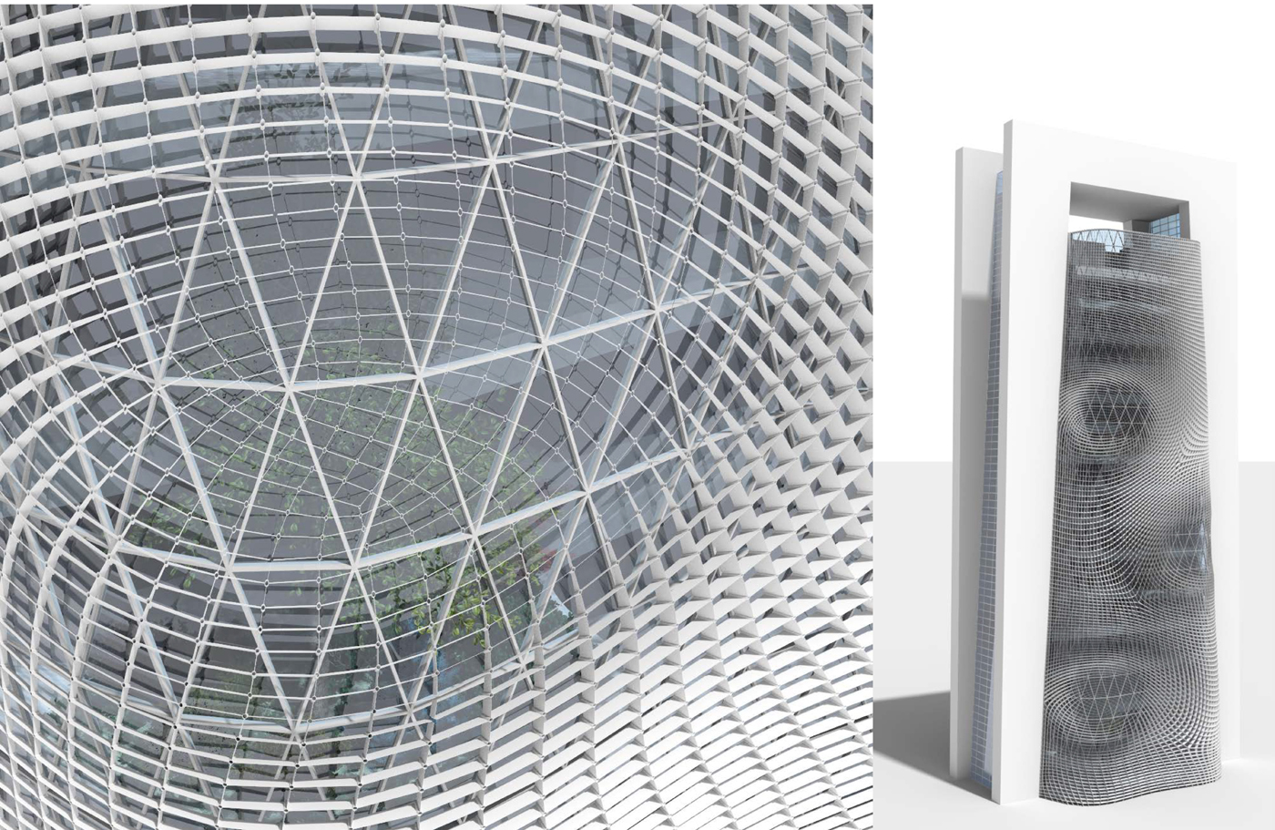
The Smithsonian institute in Washington, designed by Foster + Partners shows an interesting support structure for the glass roof. It represents an arrangement of quadrilaterals which follow the edges of a quad mesh and which actually constitutes a torsion-free support structure.
On Fig 2, we see how light interact with the beam system which has been devised below the quad mesh surface. We see clearly how the beams catch the light. Let’s imagine an optimization of the orientation of the beams to actually block or redirect the sun. This optimization constitute a lighting system that could produce shade if the facets are oriented to block the sun at certain hour or a lighting system that actually redirect the sun rays using a reflecting material with the proper orientation of the “beams”. The whole thing would be even better if in keeping with interesting connectivity properties such as torsion free, at the nods.
How it works
In other words, the topic is to optimized planar fins arranged along the edges of a quad-dominant base mesh, itself covering the reference design surface. We consider structures whose geometry is hierarchically set up as follows:
- The first element in the hierarchy is the reference design surface, which may be any freeform shape.
- Secondly, the reference surface is panelized by a quad-dominant mesh, which is referred to as the base mesh.
- Thirdly, planar fins are arranged along the edges of the base mesh such that in each vertex the planes of the fins / beams nicely intersect in a common node axis.
The primary hierarchy – the reference shape – is given, while the second and third hierarchies are to be determined by geometric objectives like maximal shading or the guiding of light by reflection. It turns out that these second and third levels (mesh and fins) are intimately connected to each other and cannot be chosen individually and independently. The total of all three levels together is called a torsion-free support structure. (Again more geometric details in the articles)
Let’s focus on the application and mostly the potential interesting properties. First we will look at a facade configuration, to continue to describe the properties, then we will look into a roof application and then come back to a facade application with some more properties and finally in the final part we will look into potential fabrication aspect of this grid.
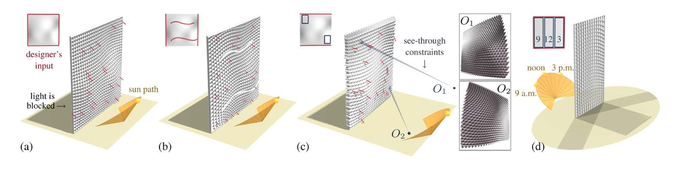
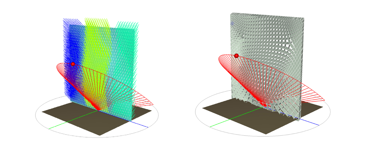
- A : blocking of light at a certain hour
- B : Blocking + orientation of the mesh according to a designer input ; here a wavy stroke on the surface
- C: see thought constrain to privileged some particular view point + still shading
- D: specific optimization with 3 target hours on the same mesh
As B, C, D show different types of constrains can be applied at the same time. For C, Fig 5, privileged point of views and maximum shading are fulfilled at the same time. It is possible to see the sky or a portion of the sky , as well as a landmark in the landscape while the sun is full blocked during the worst part of the day, noon plus or minus 1 or 2 hours, for the worst month of the years. Obviously, during the rest of the year, when light is beneficial, it can penetrate while keeping the view point always visible.

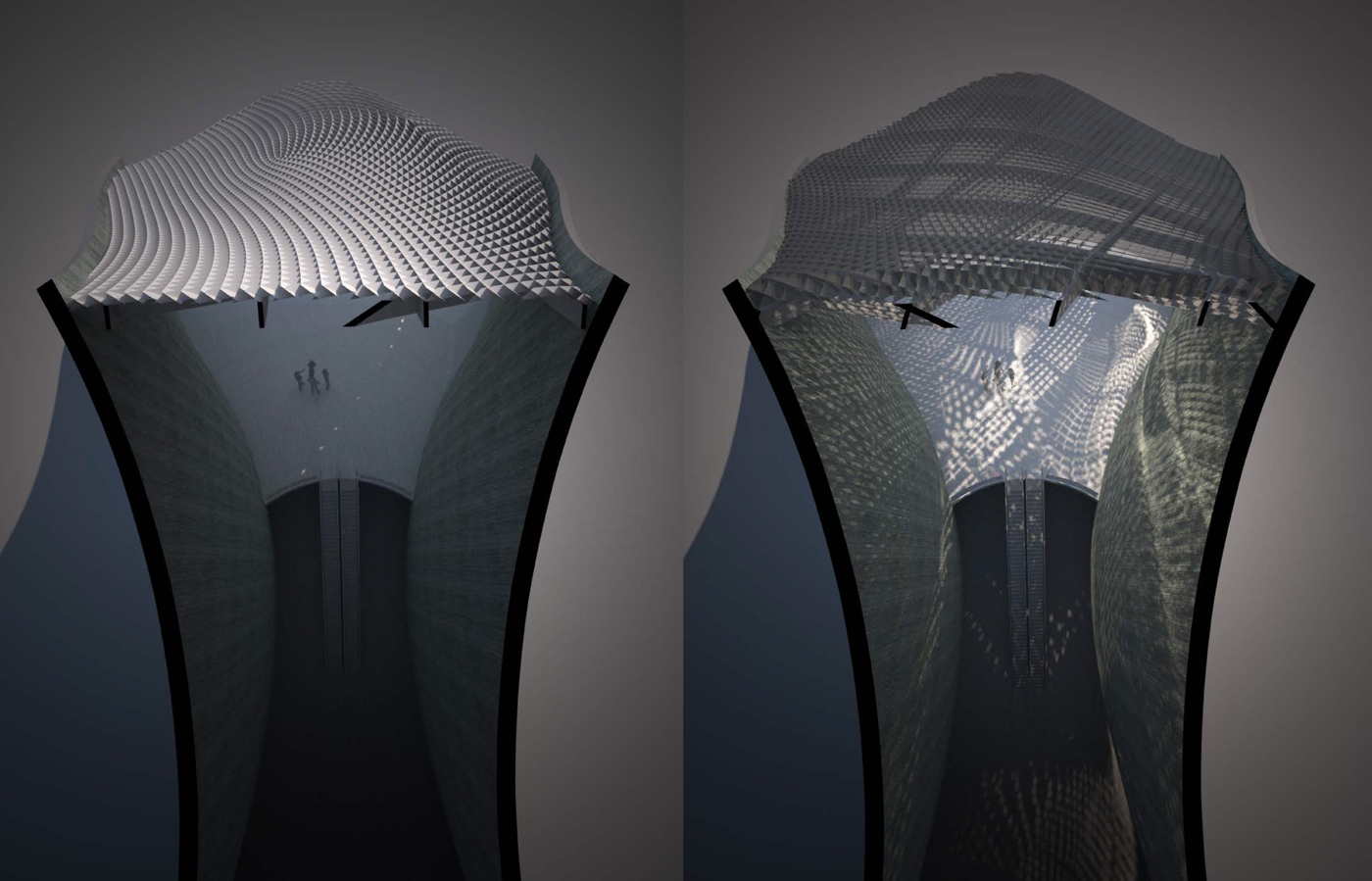
Subway entrance
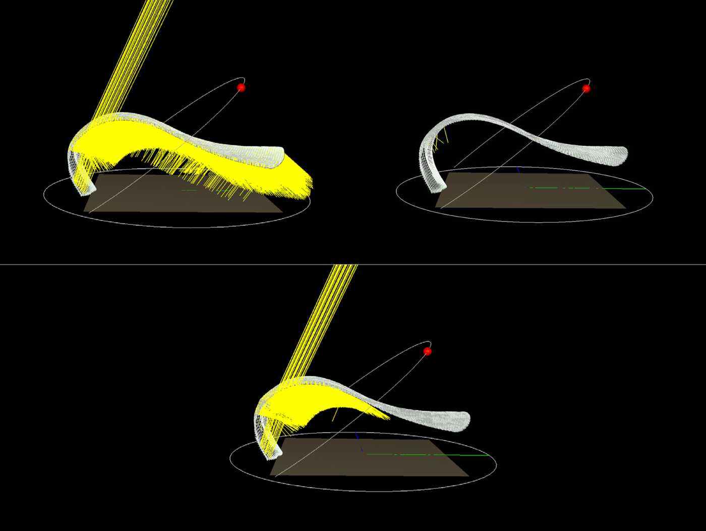
A set of studies was carried upon of imaginary subway entrance with a large canopy in the front facing south and an access to the track below through escalators. The idea was to use the grid as a lighting system that would create some shading in the front portion and redirect natural light toward the underground level in the second portion of the canopy .
We studied 3 different mesh
- full blocking of light full redirection of light toward the lower floor, using reflecting fins mixed solution of (2) serie in the front part and the (3) serie in the back part

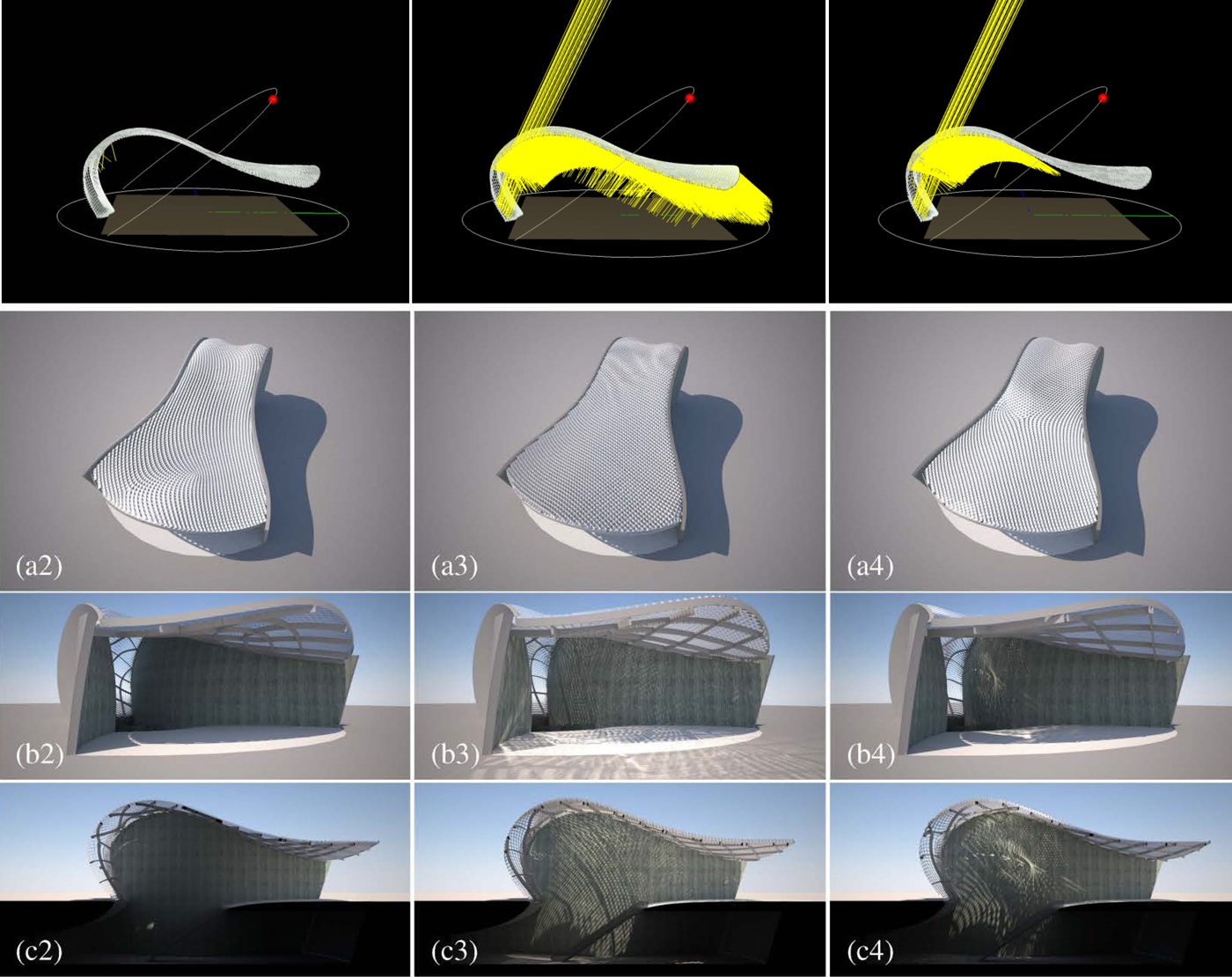
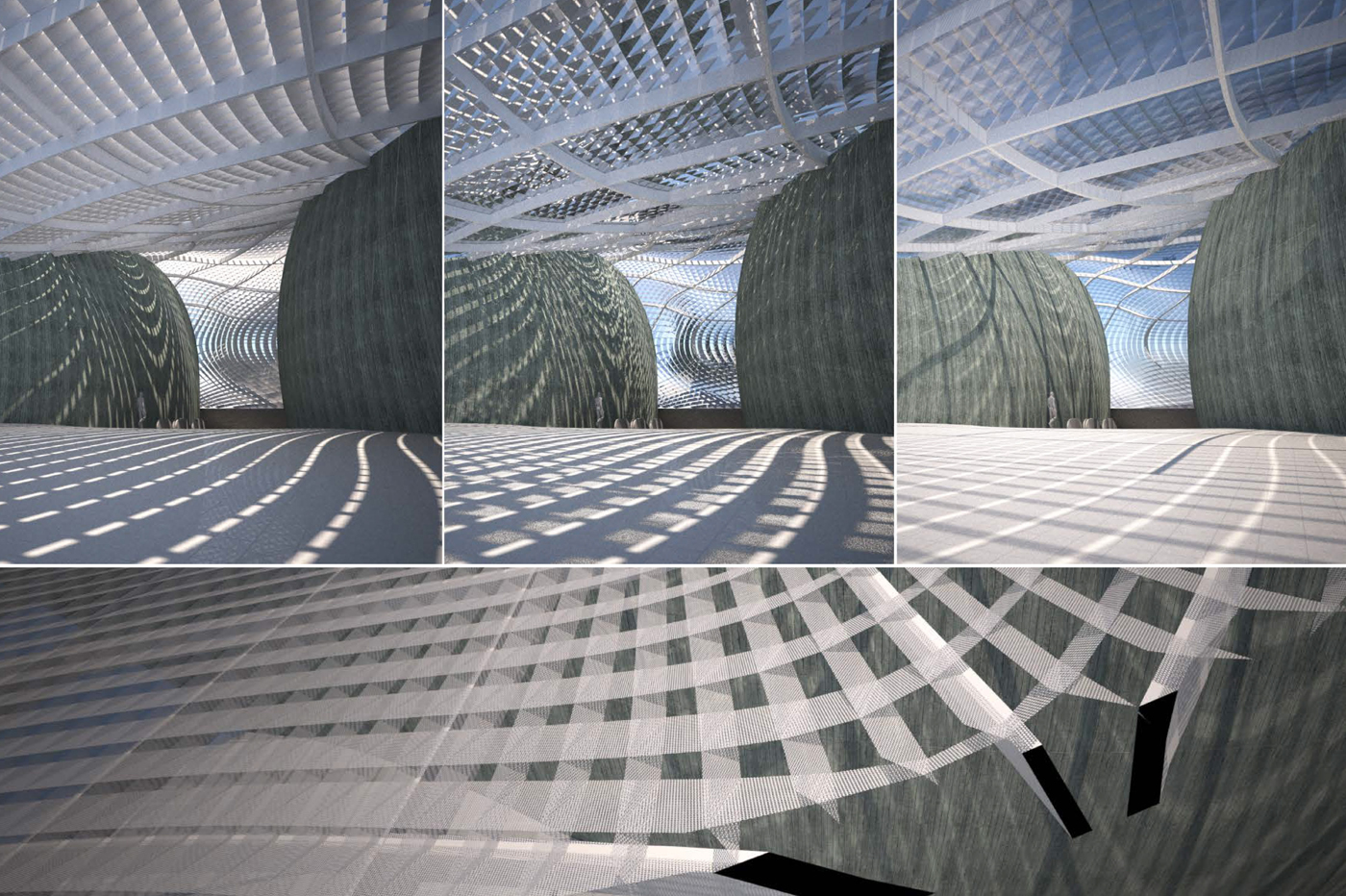
The benefit of perforated the plate is double:
- letting more light in but keeping a quite efficient shading coefficient , which is adaptable depending of the density of perforation
- the reflection of the sky onto the mirror portion which is was already giving the impression of really seeing the sky in scheme 2 is enhance because of the perforation which give of direct view of the sky (not only a reflection) the otherwise quite opaque mesh in this direction (scheme 1) seems not only lighter but more even and smooth, because of the complex interaction between direct and indirect light, and its multi- reflection.
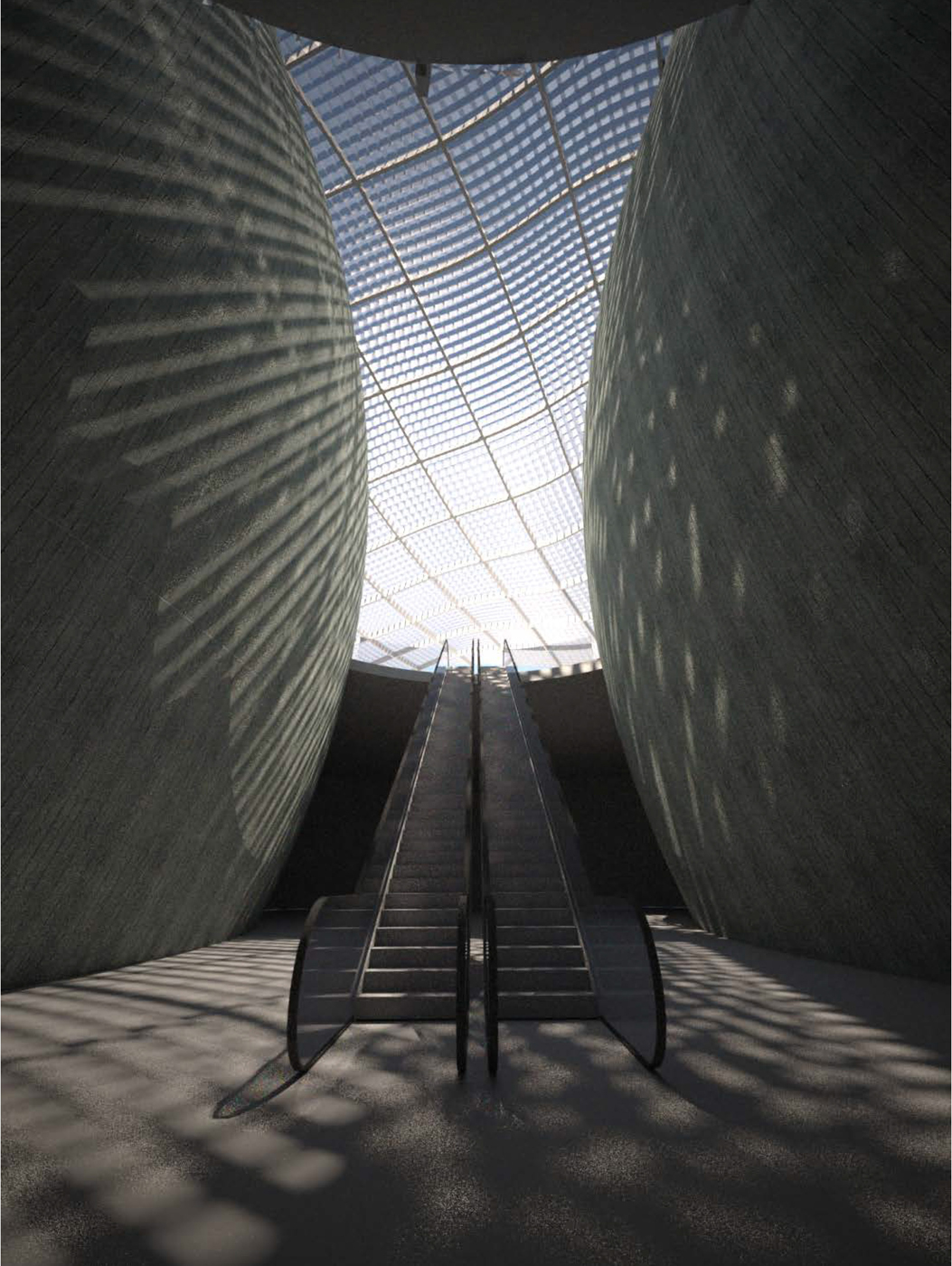
It is even more obvious in the next figure Fig 13 It would be interesting to carry some measured analysis of the light level that one can get depending of the different material. The choice of material can quite certainly participate to the efficiency of the lighting system.
With reflecting optimization on the left, with white material for the reflector, we keep the see-through effect but obtain a light veil effect due to the illumination of each quad orientated toward the light even if the shading is still provided. And if the reflectors are actually mirror finish we can actually see a reflection pattern on the ceiling where the light is aiming.

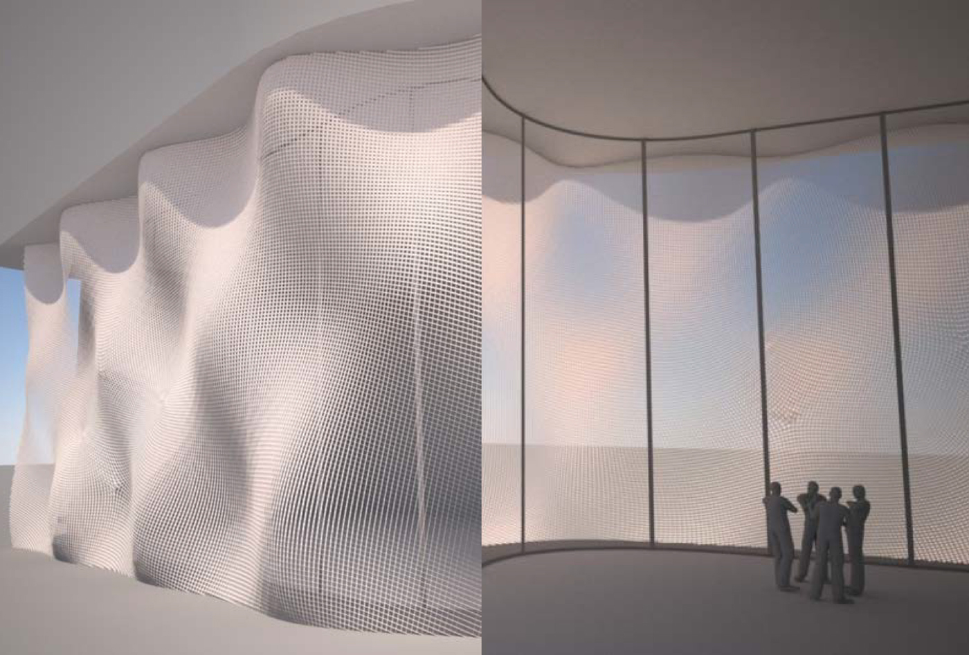
Embossed Facade
For the final example, we used a large embossed surface as a generating surface which covers the whole facade of a lobby for a tower.
Regardless of the scheme, the porosity of the mesh is quite noticeable even with a surface which is undulating so much. Porosity, not to say “transparency” from inside to the outside, is comparable to the one from a metallic mesh or tissue in similar.
On the top right, the scheme is for shading and on the bottom right, with a mirror finish material, the scheme generates a nice caustic pattern on the ceiling. At this scale od mesh, the idea of redirection can be very attractive, not just to create a caustic pattern which has the advantage to really show the light projection, but to push light far into the building, the mesh behave as thousands of micro light shelves which are regardless of the overall shape of the envelop redirecting light toward the ceiling or the back of the room. The rendering setting for images simulation are exactly similar, and without further analysis, one can already see a strong difference in light levels.
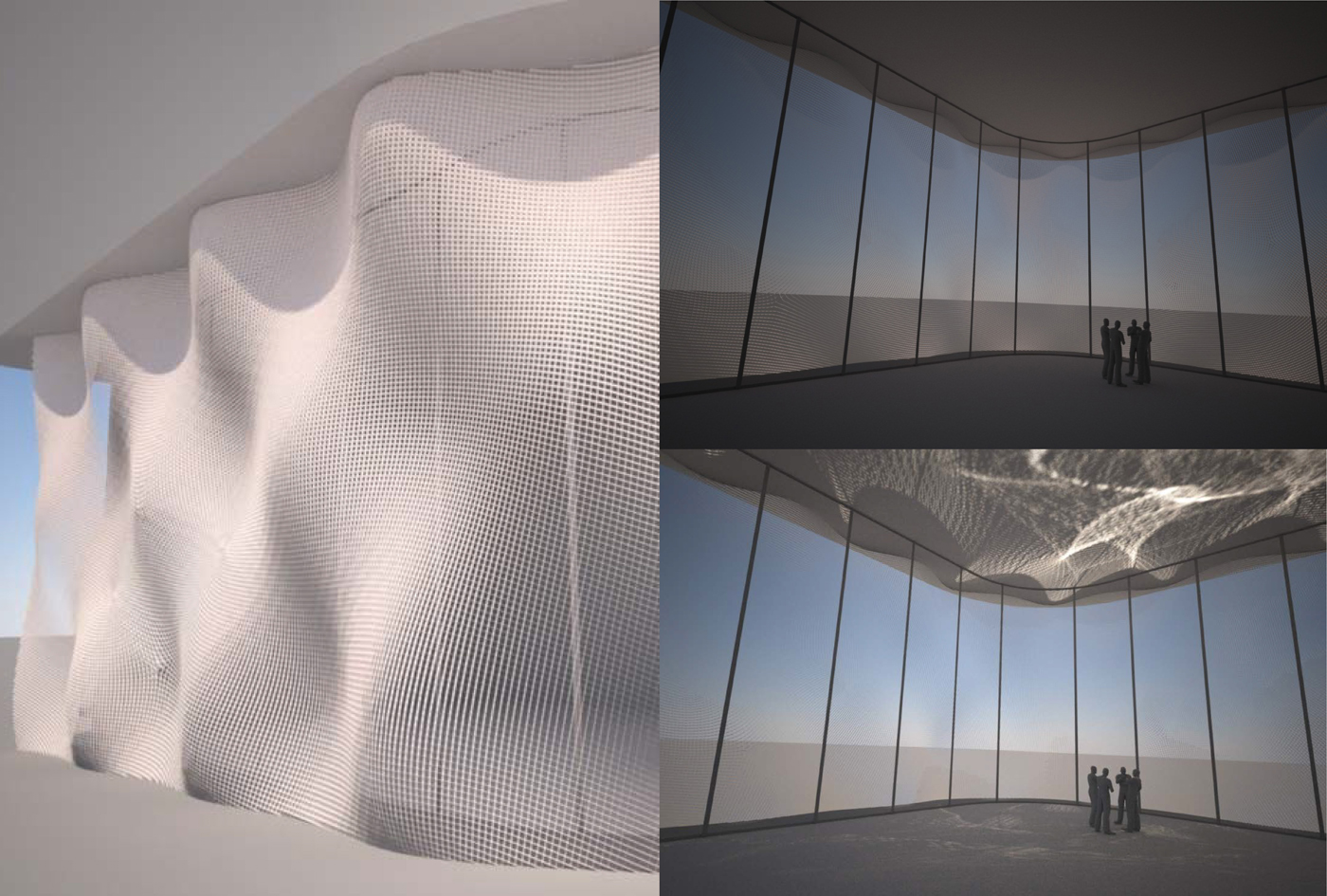
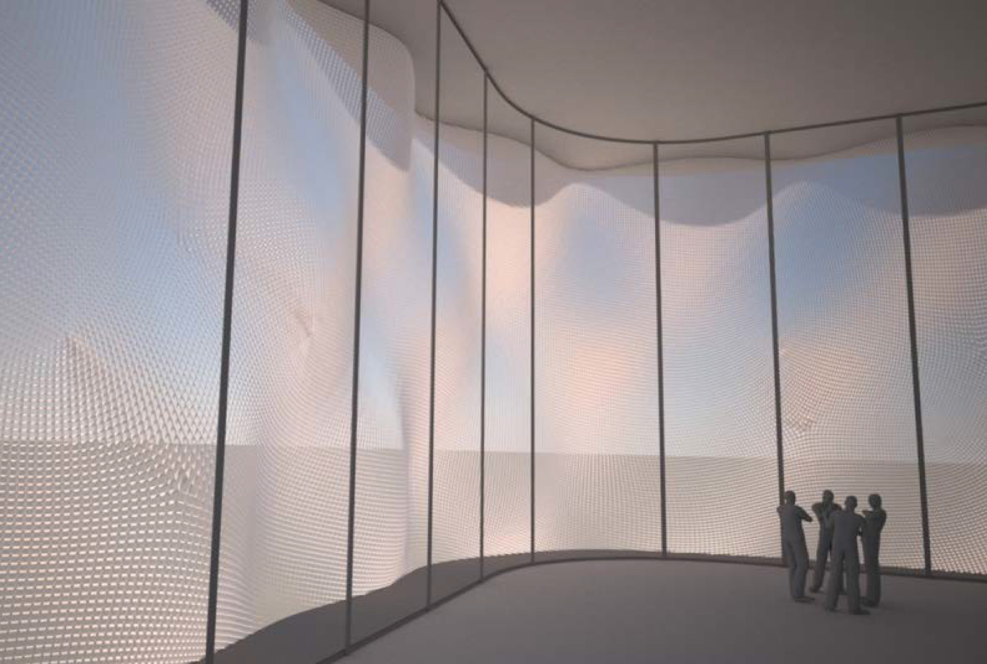
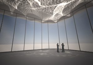
Fig 16 shows a mesh with a white opaque material, it is optimized to be a reflective mesh, so the quad are oriented toward the sun and such the light is reflected inside toward the ceiling to bring more light in. Again it is very striking to witness not only the light level which are higher, but also the transparency of the mesh from inside, but also the mesh has acquire a lightness that it did not have before, it behave like a veil that seems to float in the space. This is due to some kind inversion of shading, like the negative of argentic photograph, the shadow area appear white, as if it was lit from below. It gives a very strange and un-natural lighting source as would say Henri Alekan. This type of lighting are very often use in SCI-FI movie (this will soon be a post)