Abstract. Caustics are captivating light patterns created by materials bundling or diverting light by refraction or reflection. This paper was presented at Advances in Architectural Geometry 2012 Paris
The purpose of this post is to go a bit more in details from what was possible when writing the paper and give a bigger part to architecture, fabrication and application of the research since this is the part I took the most part into.
First of all, it is important to remind what a caustic is. This topic has been discussed in several post in this website but may be the simplest way of describing is to refer to a great book extract from a great book called Color and Light in Nature from David K lynch and William Livingston published by Cambridge university press isbn 0 521 77504 3 paperback p93 and 94. ” Water ‘s wavy surface can be thought as a serie of positive and negative lens. The positive lens focus sun light onto the bottom creating the bright network. The negative lens refract light beam and increase contrast of the network”
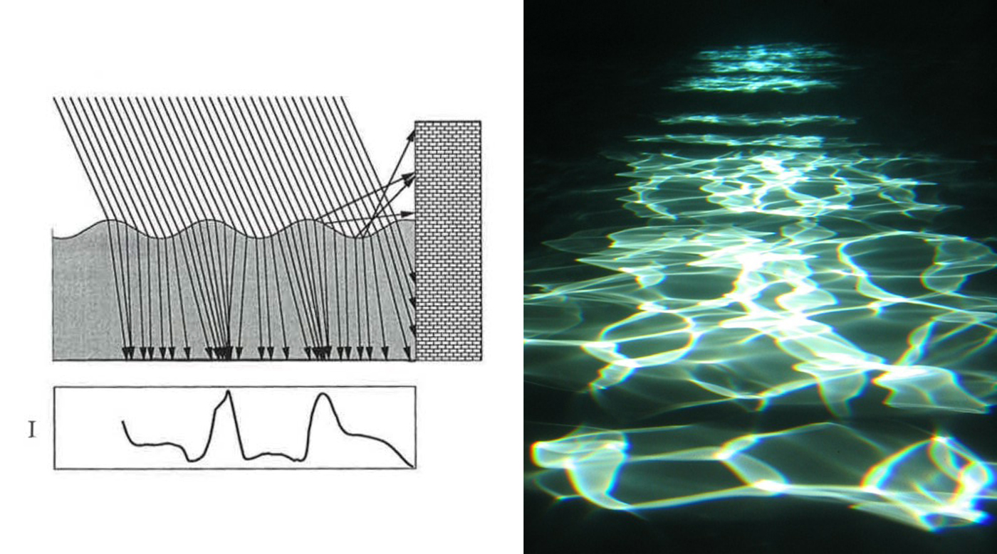 Fig 1: Caustics Principle
In the paper, we wrote that “The term caustic is derived from the latin word causticus and the greek kaustikos meaning “burned”. In optics, caustics refer to singular concentrations of light that can indeed lead to burns, as anyone who has experimented with a lens in bright sunlight might confirm. In our context, we consider as a caustic a pattern of light on a (mostly diffuse) surface that is created by focusing and diverting light through a glass object (Fig 1, left).
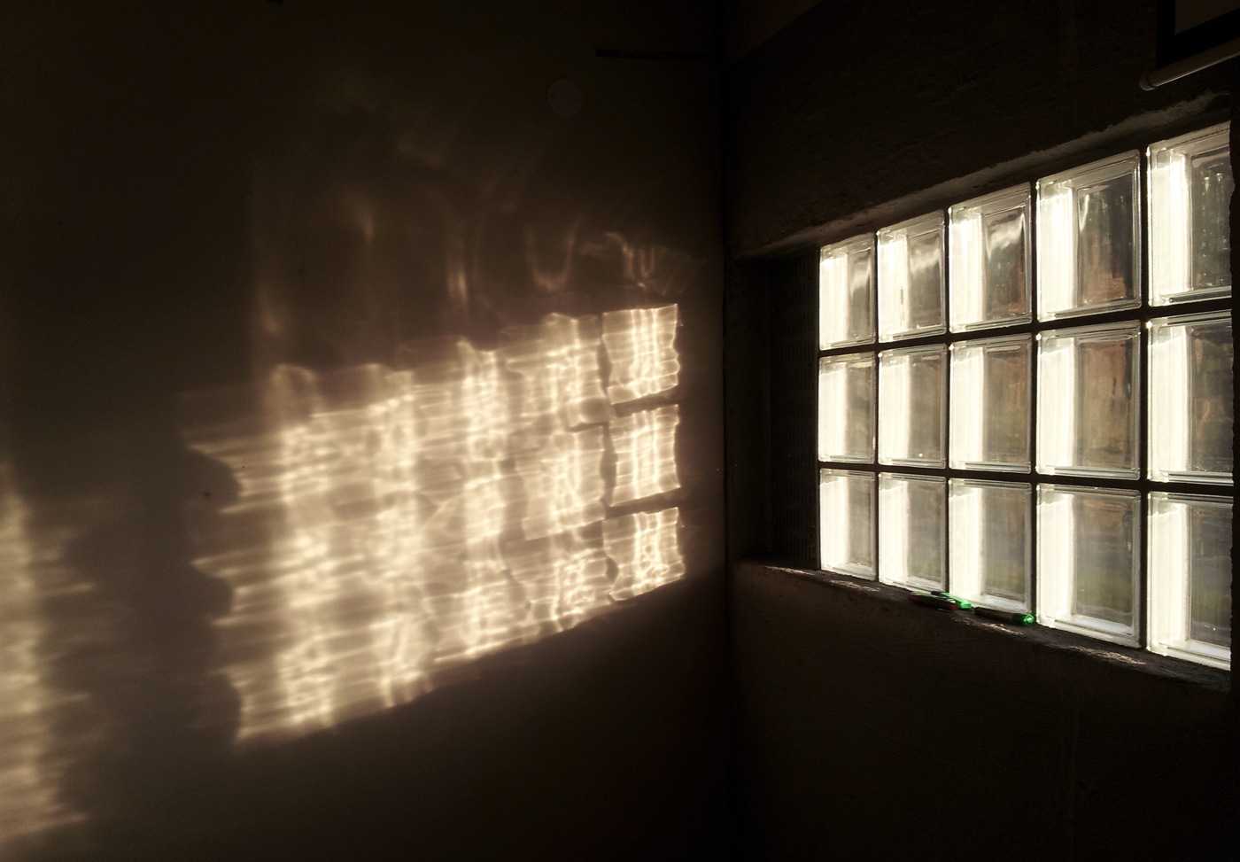 Fig 2: The glass blocs are typically made of even surface , here with the very low sun of norvegia projected into the room
We come across caustic projections very often in our everyday life. They are usually formed by uneven glass surface such as Fig 2 for a refractive caustic or Fig 3 with reflective caustic.
 Fig 3: The caustic projection come from mirror coated insulated glass The rollerwaves of the tempered glass are clearly visible. The sun light is hitting the mirrored glass and is projected onto the building across the street. (Image Courtesy of S.Aubry)
Caustic projection are often seen with water either reflective or refractive and seldom used as an architectural feature.
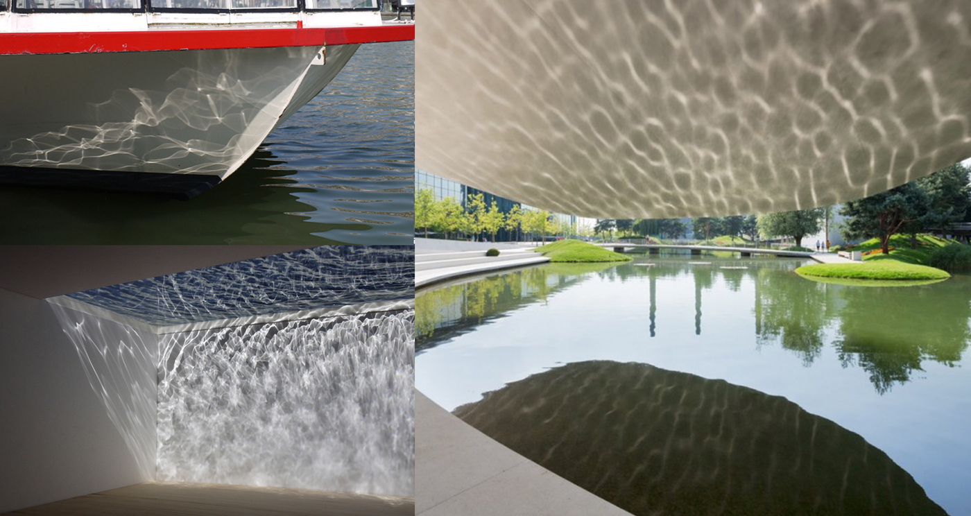 Fig 4: on the bottom left, Timescape the water ceiling, on the right the Porsche pavilion from Henn Architecten
Marc Pauly and his collaborator Thomas Kiser wrote an algorithm which enable them “To control the shape of a caustic pattern generated by a specular [or refractive] surface, …[they] need to solve the inverse problem: how can we change the surface geometry, such that incident light is redirected to produce a desired caustic image” .The algorithm is taking in consideration the Snell – Descartes law of refraction for a refractive medium. Fig 5. This can also be done with an opaque reflective medium such as silver, mirror coating or stainless or aluminum mirror polished, using the law of reflection.
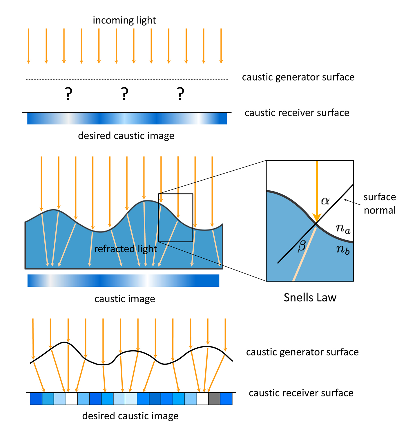 Fig 5: Principle diagram
“The geometric setup for our computations is shown in Fig 6. We require a precise specification of the direction of incoming light, as well as the location and orientation of the caustic generator (the glass object) and the caustic receiver. We model the curved surface of the caustic generator as a discrete height field, that is, a regular grid of displacement values over the plane. The desired light distribution on the receiver is specified as a pixel grid of intensity values. Given this intensity profile and the geometric specification of the setup described above, our algorithm solves for the height values of the caustic generator, such that the resulting surface of the refractive object redistributes the incoming uniform light to match the given intensity profile. The solution is obtained by deforming a discrete photon mesh to reproduce a given image. In order to refract rays on the specular surface such that they intersect the receiver at the designated points, we invert the laws of light transport and refraction to adjust the normal field accordingly. Once the surface normals are computed, we solve for the continuous surface that best fits the normal field.
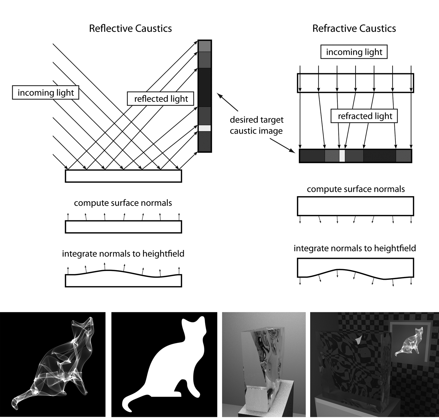 Fig 6: Principle diagram
On paper, the simulation showed a piece of transparent material (glass, acrylic, polycarbonate…) with a free from surface which produce an image when a light is shine through it !! In summer 2011, we set out to find ways to fabricated a sample. We had many questions: what level of accuracy of the surface is really necessary ? how would a small variation in the index of refraction between the calculated value and the actual material IOR would affect the image ? Would we find a proper light source which would be close enough to the one use in the simulation , which was a perfectly paralleled light beam.
For the production of the samples, we teamed up with Florian Rist and Raimund Krenmuller of Tu Wien department of architecture and their extended knowledge about materials and ways to machine them.
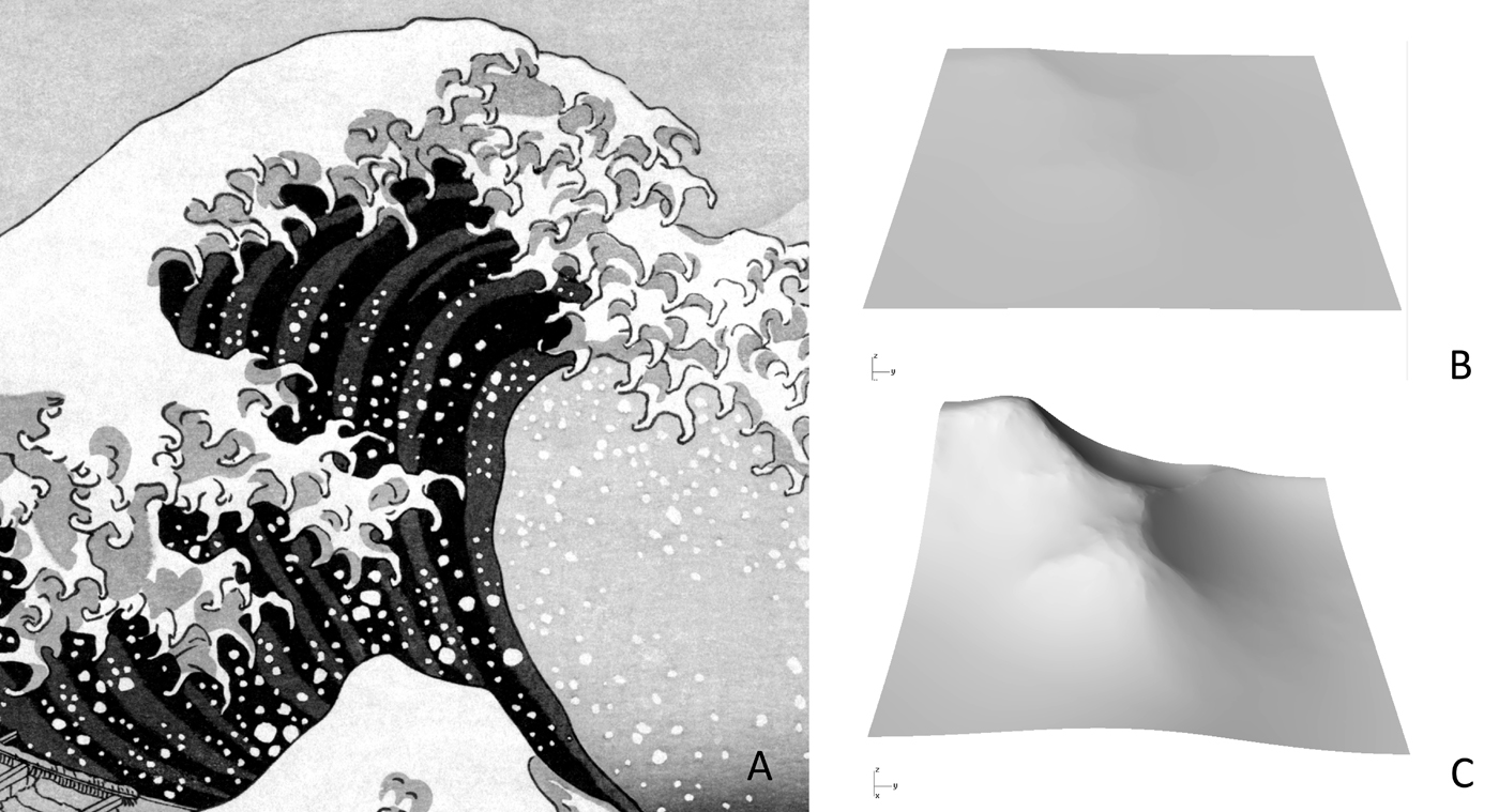 Fig 7: Alumimium Sample: (A) reference image (B) surface to be milled (C) Surface with Z X 10.
The first sample to be made was out of aluminum, with a reflective surface. It was supposed to enable the projection of the famous Japanese wood print: the Wave from Hokusai. The calculate surface of reflection had a very shallow height of field amplitude. Fig7 shows the surface with the z value scale x10 fold t.
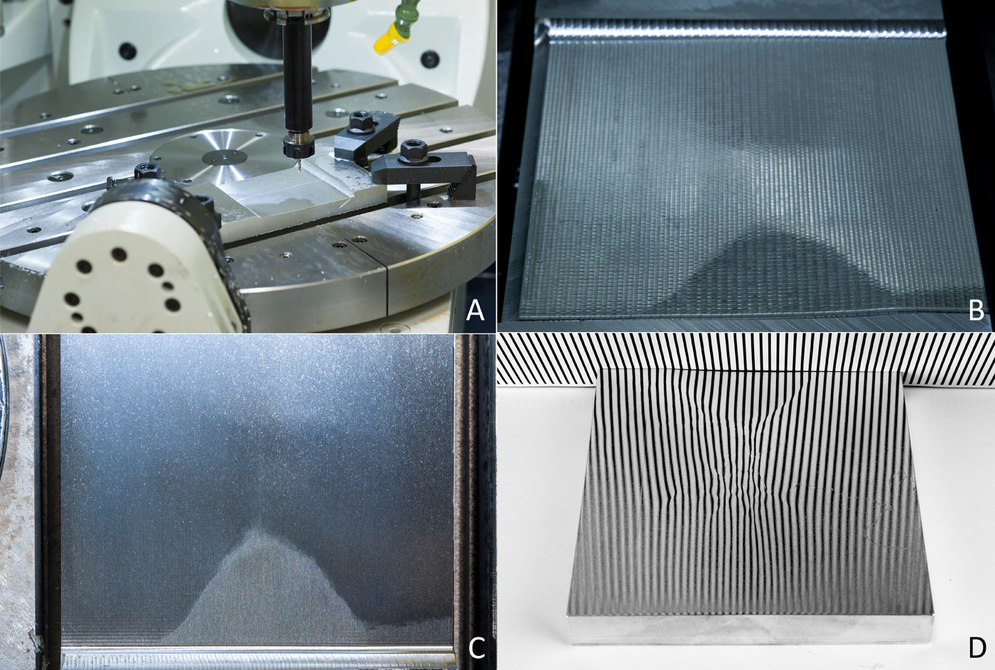 Fig 8: (A) Milling (B) First Pass (C) Final Pass (D) Fully polished
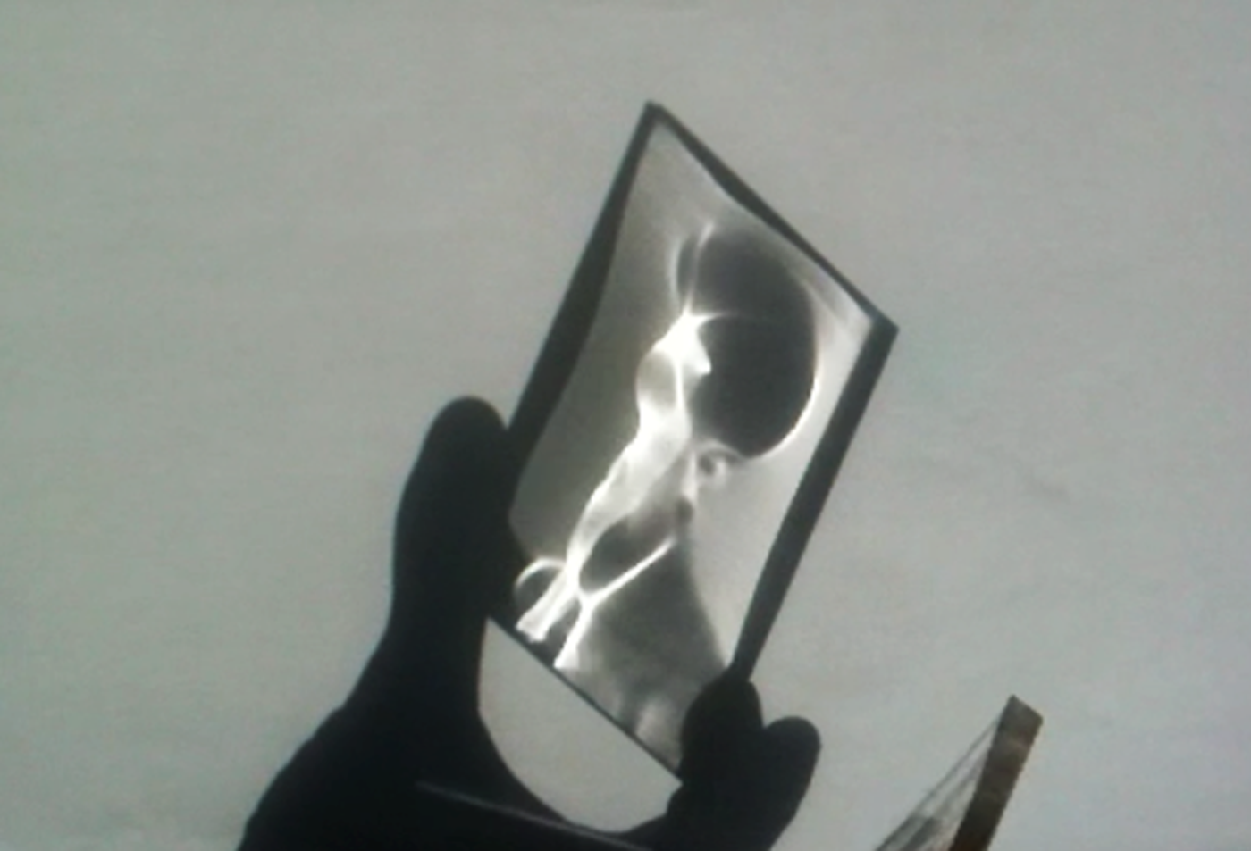
The milling was done with several pass Fig 8. Before the surface was properly mirror finished, we could already distinguish a faint shape close to the wave. Fig9 After polishing, one could clearly see the image. It appears very easily, to our surprise, the light set up did not have to be as precise as we had anticipated. It required just a flash light onto the piece of aluminum and be close enough to calculate distance to the projection surface to see the image appear. Fig 10
 Fig 9:(A) Reflection with rough surface (B) Image after polishing
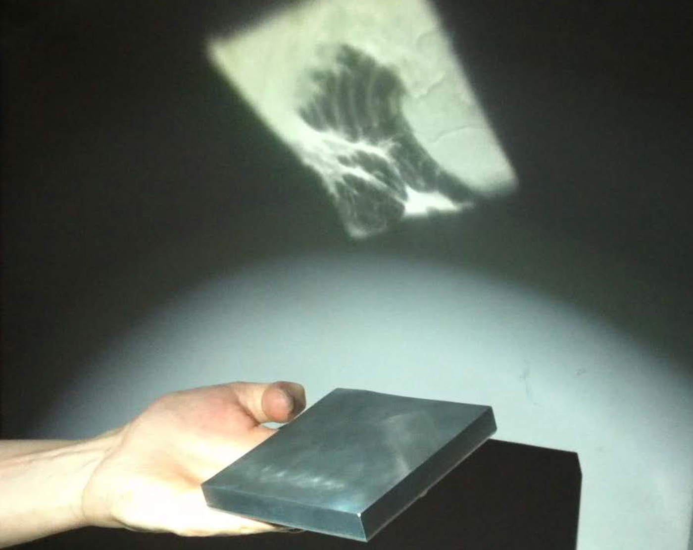 Fig 10 : Hokusai Image projection
This robustness of the appearance was very reassuring and provide a much large range of use since everything did not have to be perfectly perfect.
Further results : Extract from the GPD article
This first result was so exiting that we decide to do another sample using this time the portrait of Alan Turing for a refractive application . The Vienna team “decided to experiment with widely available and relatively cheap technologies and not rely on high-end equipment like ultra-precise CNC lathes or mills and diamond cutters as used for example by Brecher at.al [6]. All our samples were machined on a 5-axis machining center, a Spinner U620, Siemens Sinumerik 840D SL. The necessary polishing of the surfaces was performed using a small hand-held tool and suitable grinding and polishing pastes. The produced objects were illuminated either by sunlight or a LED spotlight. Neither of these light sources carries any information on the caustic image that was observed on a planer white screen. The created light pattern is solely due to the curved geometry of the refractive pieces. “
The surfaces were machined using a ball nose tool and parallel finishing cuts. The tool was tilted by a positive lead angle against the surface. Based on an analysis of the surface features, the maximum tool diameter was chosen to obtain virtually gouging free tool paths. We experimented both with direct machining by milling and grinding, as well as indirect casting using a mold. For both processes we created samples using glass and plastics to evaluate the fabrication processes for different material properties.
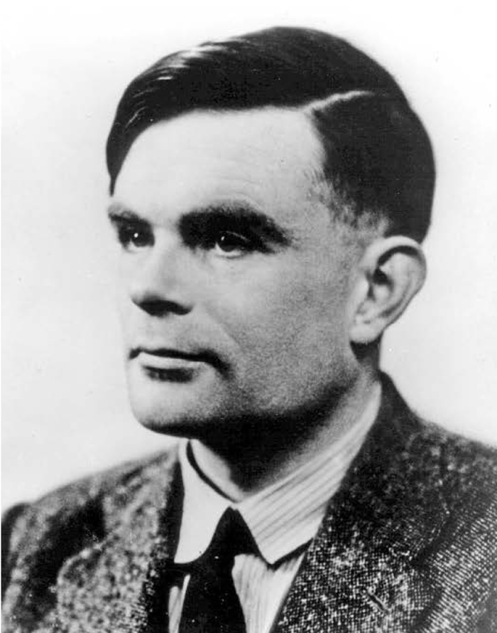 All samples use the same target caustic image of a portrait of Alan Turing shown in Figure above
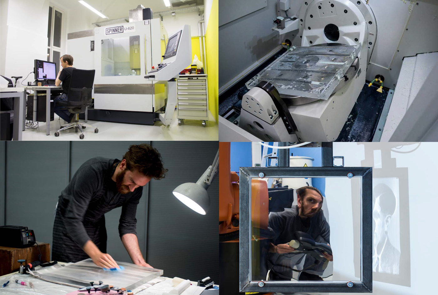 Fig 11: Acrylic fabrication
Sample 1: PMMA milling: Fig 11 shows the fabrication of an acrylic sample milled from a 500x500x30 mm³ PMMA block. The surface was machined using a 12 mm solid carbide ball nose end mill at a lead angle of 20°, resulting in an effective tool diameter of 4.1 mm. The distance between the paths was 0.2 mm. Total milling time was about 20 hours. After milling, the piece was sanded manually and polished using diamond grinding pastes. The finish was done using a special PMMA polish paste. As illustrated in Figure 5, this sample confirms that the calculated surface does indeed create the intended caustic very accurately. It shows that our system is robust enough to cope well with the simplifying assumptions made in our computational framework, as well as with the manufacturing tolerances and suboptimal lighting.
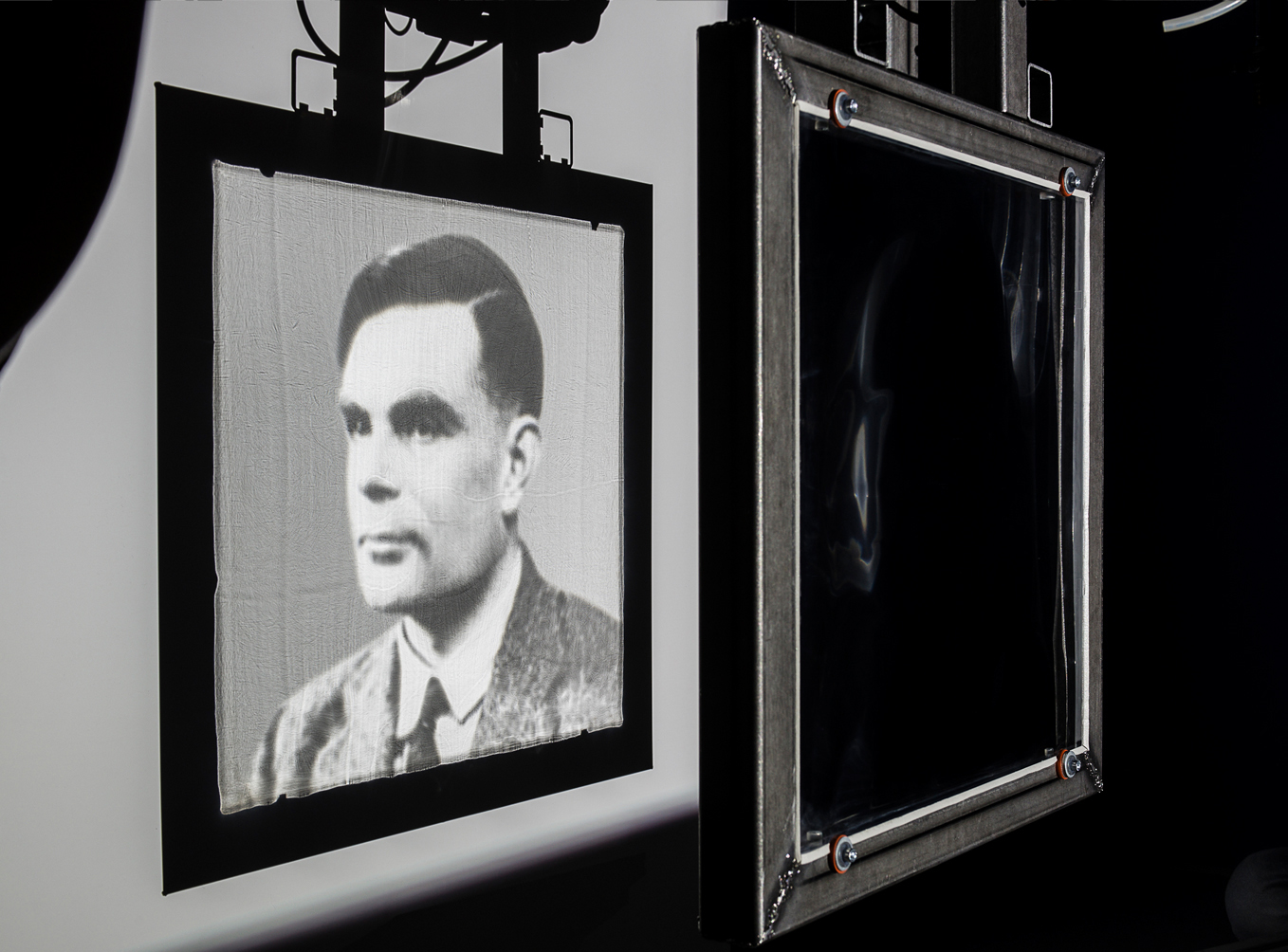 Fig 12 Caustic generated by the milled 500 x 500 mm PMMA Sample 1.
Stainless steel mold for casting.:While the previous sample was directly manufactured, the following experiments evaluate casting processes aimed at mass-production. For this purpose we created a stainless steel mold with a net size of 120×120 mm² (Fig 13). Despite using a different tool and suitable machining parameters, the steel mold was essentially produced the same way as the PMMA piece.
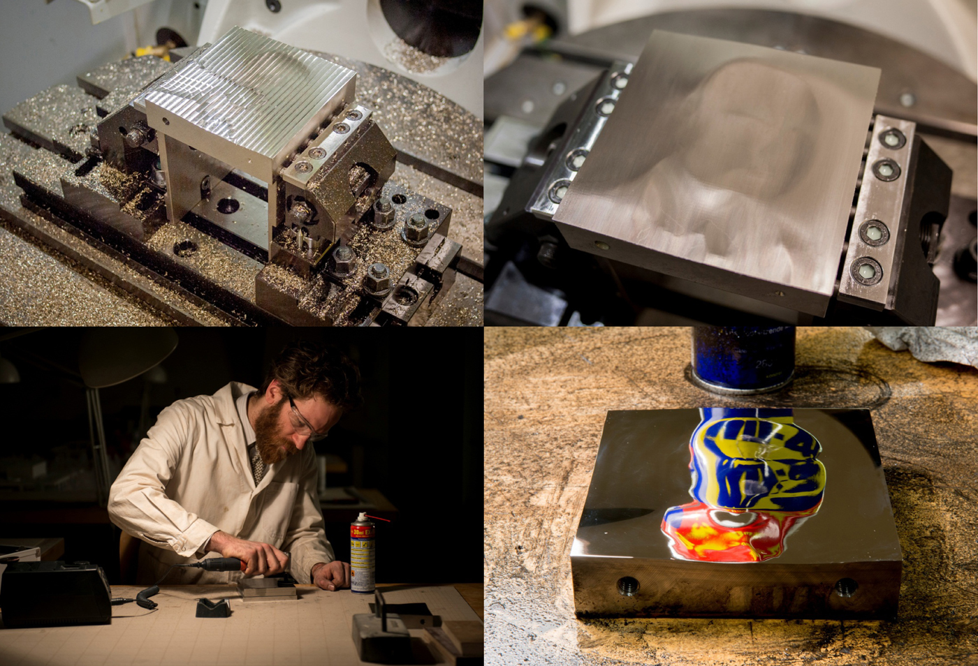 Fig 13 Steel mold. Top Left: first pass. Top Right: finer mill before polishing. Bottom Left: mold assembly. Bottom Right: A checker board is used to visualize the small surface elevations of the mirror polished surface
Sample 2: Resin cast: The stainless steel mold was first used to cast clear resins (Fig 14). The main reason for these casts is to test the mold properties with a simple and reliable casting technique. We used smooth-On Clear 221 and Clear Flex, both polyurethane based two-component resins before testing with actual glass.
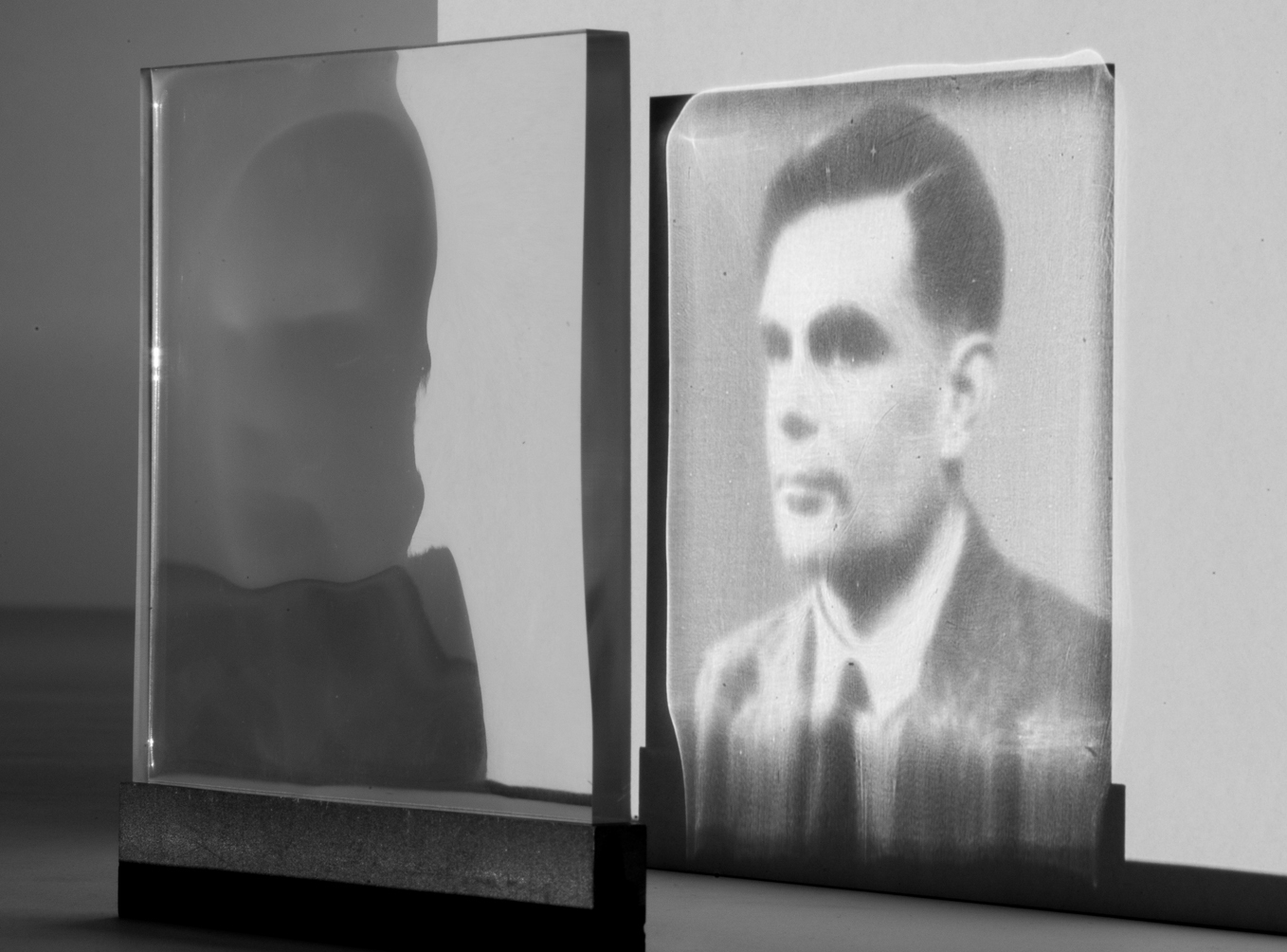 Fig 14 Caustic generated by parallel light through the Sample 2 made of cast Resin.
Sample 3: Glass grinding: For certain architectural applications PMMA might not be durable enough. Therefore, we conducted a series of experiments to produce caustic generators in glass. While glass is difficult to mill, it is relatively easy to grind, so we slightly adapted the previously used machine to create a 140 mm diameter Schott Borofloat glass sample in the same manner using a standard 8 mm diamond coated ball grinder. As expected, machining and polishing times increased significantly compared to PMMA. Fig 16 shows the result.
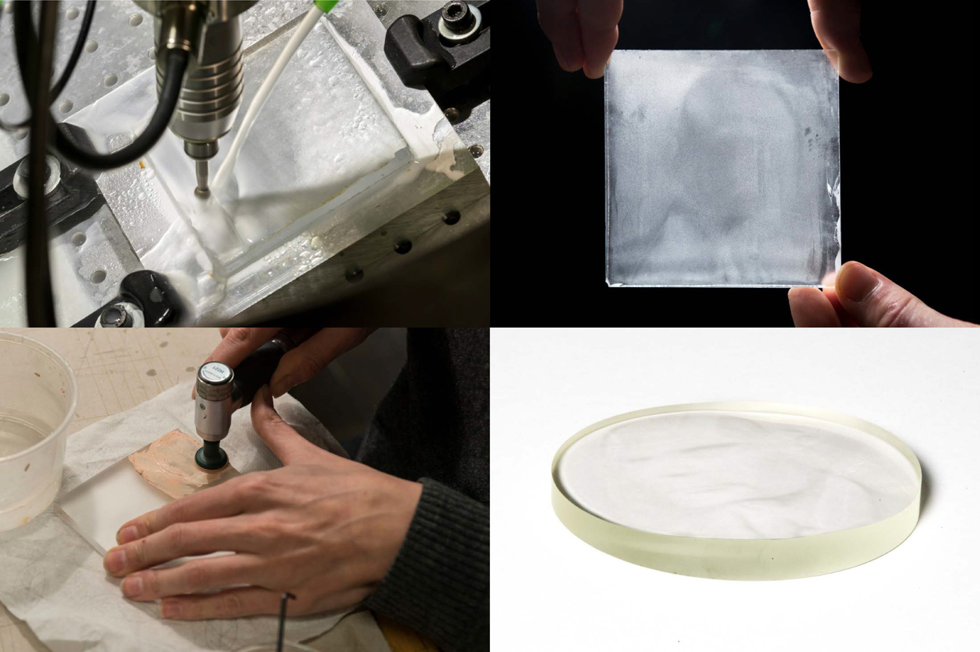
Fig 15 polishing and grinding glass Fig 16 Caustic generated by the sample 3 produced with glass grinding. Insufficient polishing leaves some speckle-noise on the caustic image.
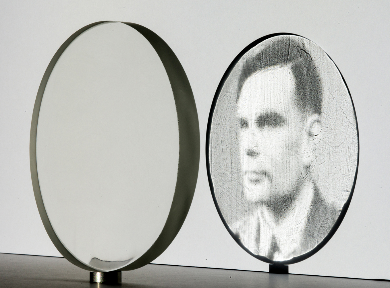 Fig 16 Caustic generated by the sample 3
Sample 4: Glass slumping We did a very basic test to reproduce the caustic generator from glass by molding using slumping. Figure 9 Bottom Left shows a copy of the negative steel mold made from a temperature resistant mold mix. Fig 17 Top shows the results obtained by slumping two different types of glass at a temperature of 870 °C for one hour. While this technique is cheap (as the positive can be made from almost any easy to machine material) it limits the quality of surface reproduction. The overall accessory is good, but the inherit roughness would make time-consuming polishing necessary.
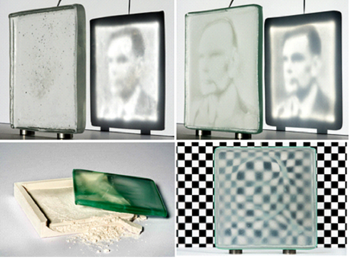
Fig 17 Glass slumping. Top Left: caustic generated by slumped Bullseye glass. Top Right: caustic generated by slumped regular float glass. Bottom Left: fire resistant mix mold with a slump piece. Bottom Right: checker board visualization.
Since then we have worked further with different glass types and obtain some better results. This is currently being developed.
2013 June: M.Pauly, M. Eigensatz, P.Bompas, F. Rist, R. Krenmuller, Controlling Caustics , Glass Processing days Tempere Finland 2013, page 213, Proceedings
2012 September:T. Kiser , M. Eigensatz, M. M. Nguyen, P. Bompas M. Pauly ,Architectural Caustics —Controlling Light with Geometry, Advances In Architectural Geometry 2012 Springer WienNew York , page77, Proceedings AAG 2012
More infos and videos are availlable on this websiste. http://lgg.epfl.ch/caustics
“Light Tamers” – Article by Philip Ball in the New Scientist – see also the online version of the article