The Article below was presented at Glasstec 2014. It is co-written with Etienne Sandre Chardonnal, founder of Eclat Digital research and developper of the simulation software Ocean ( For more information about this software: http://www.eclat-digital.com/modelling-complex-glass-structures)
Abstract: This paper presents the state of the art for predicting the appearance of glass compositions ranging from typical glazing to very complex ones, using computer generated images. A case study is presented, comparing a real project, the Memorial for the abolition of slavery in Nantes, France, with a computer simulation. Then the potential of this tool for architectural design is shown with a few examples.
Introduction
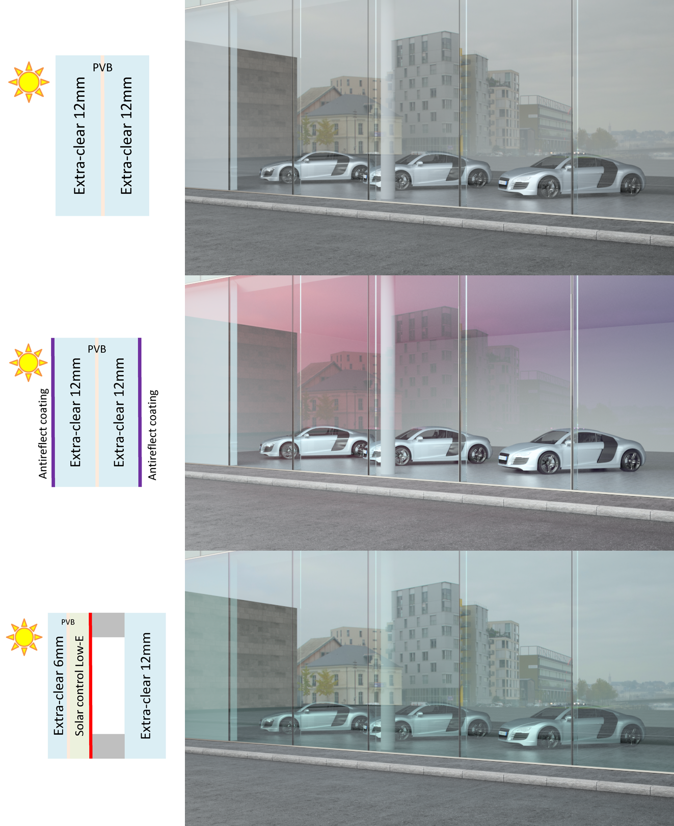
A glass envelop is nowadays very exceptionally composed of a single glass pane. Facades are made of multiple layers and it is not uncommon to find triple glazing with several coatings such as low e, solar, serigraphic frit but also micro blinds, metal mesh, in laminated glass or in the IGU cavity … Many other treatments or coatings can be applied, such as tempering, reflective, anti-reflective, anti-bacterial, self-cleaning…each of these nanometer-scale layers is affecting the transparency of glass in some very complex optical interaction. Glass composition has turned into a science but also an Art from which the identity of the building often depends. The aim of this article is to consider the engineering of transparency only from the accurate representation aspect using better tools to anticipate and design rather than represent.
Digital rendering of a complex glass composition
At an age where, one can watch a monster or robot seamlessly interact with real actor in movies, no architect, designer will consider to choose a glass composition from a digital simulation! For all other aspects but optical, structural, thermal, acoustical studies, digital simulations are used but for optical behavior of glass, there is an established and certainly justified mistrust for the tools which simulate glass in particular; rendering is more about faking than predicting reality. The usual decision process is strongly dependent on physical testing, relying on the production of dozens of samples, from which one is chosen and, in the best case, used for a full size prototype, altogether a costly process.
Usual 3D computer graphic software is not well suited for this task. An image renderer is designed more as an extremely powerful painter palette, rather than a crystal ball. It cheats on purpose with the laws of optics: who wants to make special effects for a movie with the same constraints as in the real world? Anything is possible, from removing cast shadows, to changing the lighting conditions on individual objects.
Some physical phenomena are also often omitted, because they bring no creative possibilities. For instance, the spectral decomposition of light is reduced to a RGB trichromatic approximation in most cases. The polarization of light is also neglected.
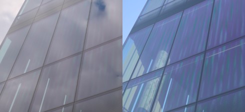
On a glass façade, light polarization may significantly impact color and intensity of the sky reflection. A computer graphic artist does not need exact computation of this value: he will manually increase or decrease the amount of reflection, or tune the color, until the resulting image matches his will. 3D renderers are meant for this: easy and free adjustment of materials and light properties, and fast feedback to see the changes quickly.
On the other hand, they cannot provide a fully accurate prediction of how a material will look like, in a given environment and under a given lighting. For instance, a full spectral calculation is required for accurate color prediction: this was demonstrated in [1]. A full spectral render consists in providing spectral properties for both materials and light sources, and calculating the result wavelength by wavelength, converting to RGB pixel values image at the very end of the process.
Similarly, it was shown that polarization affects the appearance of a glass building under clear sky [2]. The same article proposes a polarized sky model. [3] establishes most equations for polarized ray-tracing simulations, including birefringence effects.
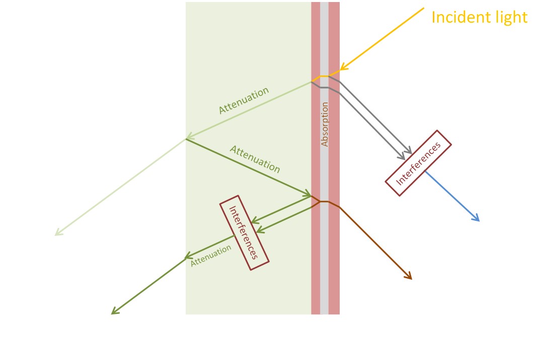
Lastly, glass and coated glass is complex to simulate due to its semi-transparent nature. Every interface splits an incident ray into a transmitted and a reflected ray, leading to a very large number of light paths, which all contribute to the overall colors and brightness levels. This will require an efficient sampling of the evaluated light paths, to keep computation times realistic. Several algorithms have significantly improved that point in the 90s [4].
These papers, amongst others, show that simulating most optical phenomena is feasible. By combining this with precise measurement of the optical properties of materials (such as refractive index, reflection spectra, etc…), and with the processing power of modern computers, predicting the appearance of glass objects becomes possible.
Simulations are usually cheaper and faster than physical prototypes. For designing aesthetically a glass envelope, using virtual prototypes allows visualizing more variants of the glazing, at a lower cost, and in a shorter time frame. This offers a strong creative potential to the designers. Off course, physical prototypes are still required for validating the appearance predicted by the simulation, for assessing that it may be built, and for developing the façade assembly process. But making all the prototypes which “do not look good” may be avoided.
Physical rendering of a glass coating
For simulating the glazing appearance, we use Ocean 2014, an in-house light simulation tool developed by Éclat-Digital Research. It performs a fast Monte-Carlo/Metropolis integration of the light transfer equation between light sources and cameras in 3D scenes, and is both spectral and polarized.
The geometry input is a 3D CAD scene where the glazing was carefully modelled with surfaces. Depending on the viewing distance, surfaces may be simplified. For instance, visualizing the trench color of a glass pane requires modelling it as a block with its physical thickness. On the other hand, modelling a pane as a single surface with no thickness gives good results for thinner glass, long viewing distances, and if the trench is hidden by the structure or joints.
Then, geometry surfaces are given optical properties. This can range from the simplest, a constant reflection and transmission coefficient pair, to the most detailed models, using tabulated values as a function of angle of incidence, wavelength, and polarization states.
For simple surfaces, such as uncoated glass or simple thin films whose structure and composition are well known, the optical properties may be calculated analytically. For complex surfaces, such as low-E coatings, the data is measured on a glass sample using a spectro-goniophotometer. It may also be provided by the manufacturer or found on software libraries such as Windows/IGDB from LBNL. In either case, the data must correspond to the 3D model surfaces: if the pane was modelled with a thickness, the reflection/transmission values correspond to the glass-air interface. If the pane was modelled as a single surface with zero thickness, the values must correspond to the full pane.
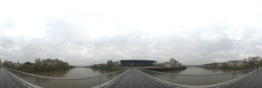
The last requirement for a realistic simulation is a lighting model. For daylight scenes, we use spherical high dynamic range pictures (HDRI) such as Figure 4 which include both environment buildings and sky, and interpreted as the radiance map of an infinitely distant light source. This approach is rather common in computer graphics and was first described by P. Debevec [5].
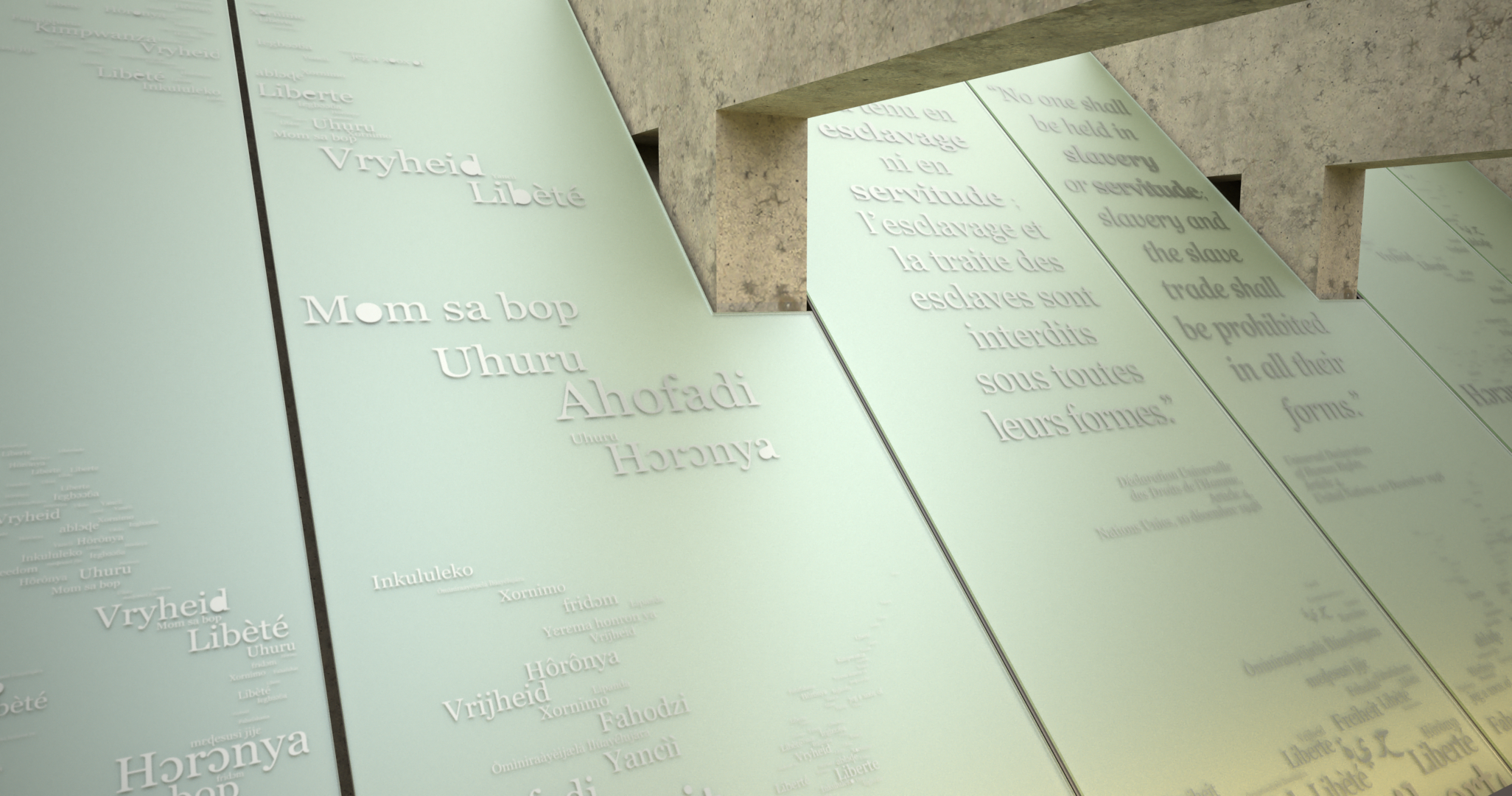
The Memorial for Abolition of Slavery, Nantes France
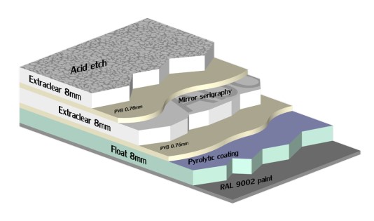
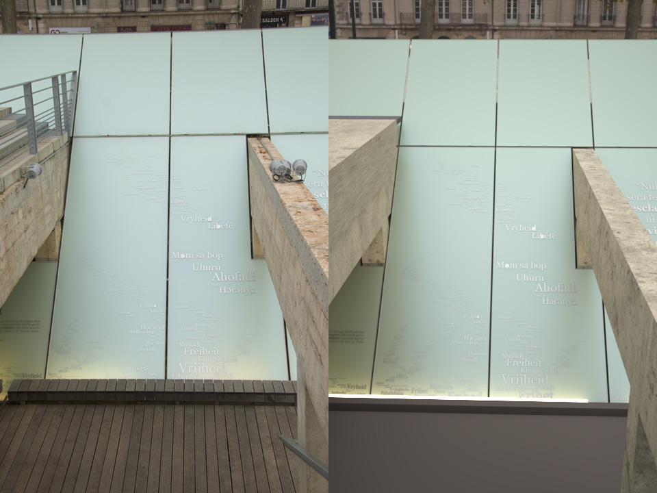
Located along the Loire riverfront in Nantes, the Memorial for Abolition of S7lavery, designed by Wodiczko + Bonder, is mostly taking place under one of the quayside where the ships were docked. A 90 meter-long underground passage evokes the captives in the ships’ holds. A series of quotations, in every language depict humanity’s long combat against slavery are set in a complex glass composition featuring three sheets of glass laminated together including coatings, serigraphy, acid etch and paints (Figure 5). This composition let the text appear sometimes dark on bright, sometimes bright on dark, depending on light conditions.
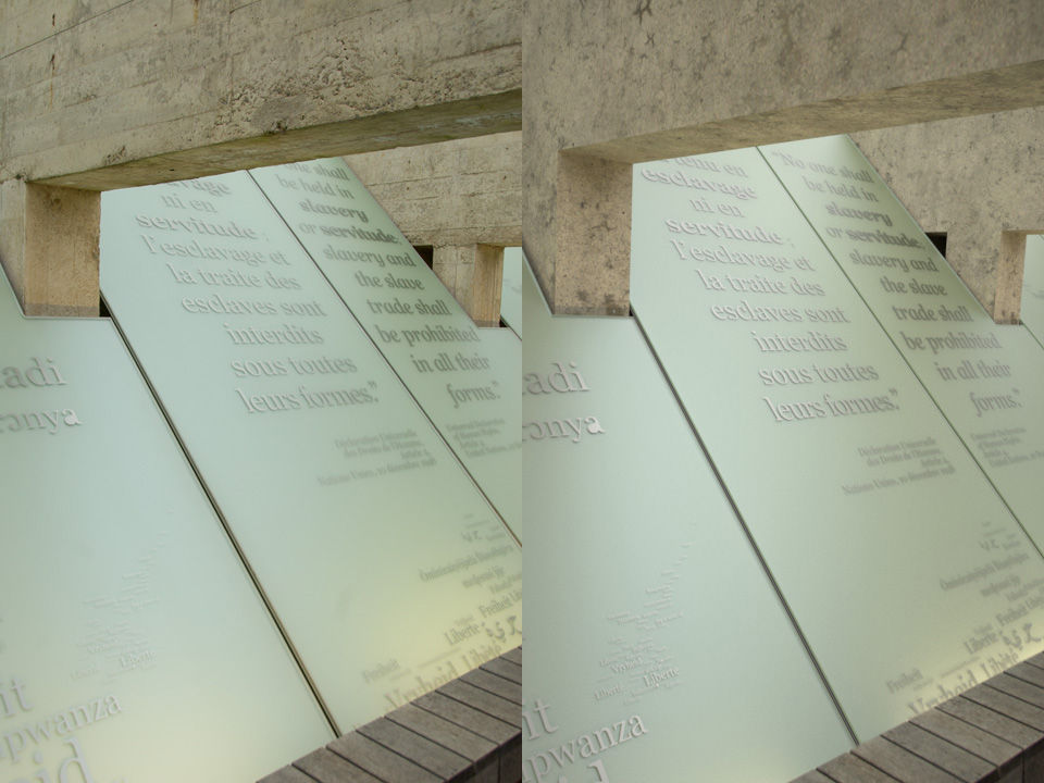
This composition is especially difficult to simulate, as most effects are caused by the multiple light bounces between the coatings, paints and acid etch layer. Below a juxtaposition of a real picture and of the simulation which show the level of accuracy which can be obtained by such renderings.
Simulation as a design tool
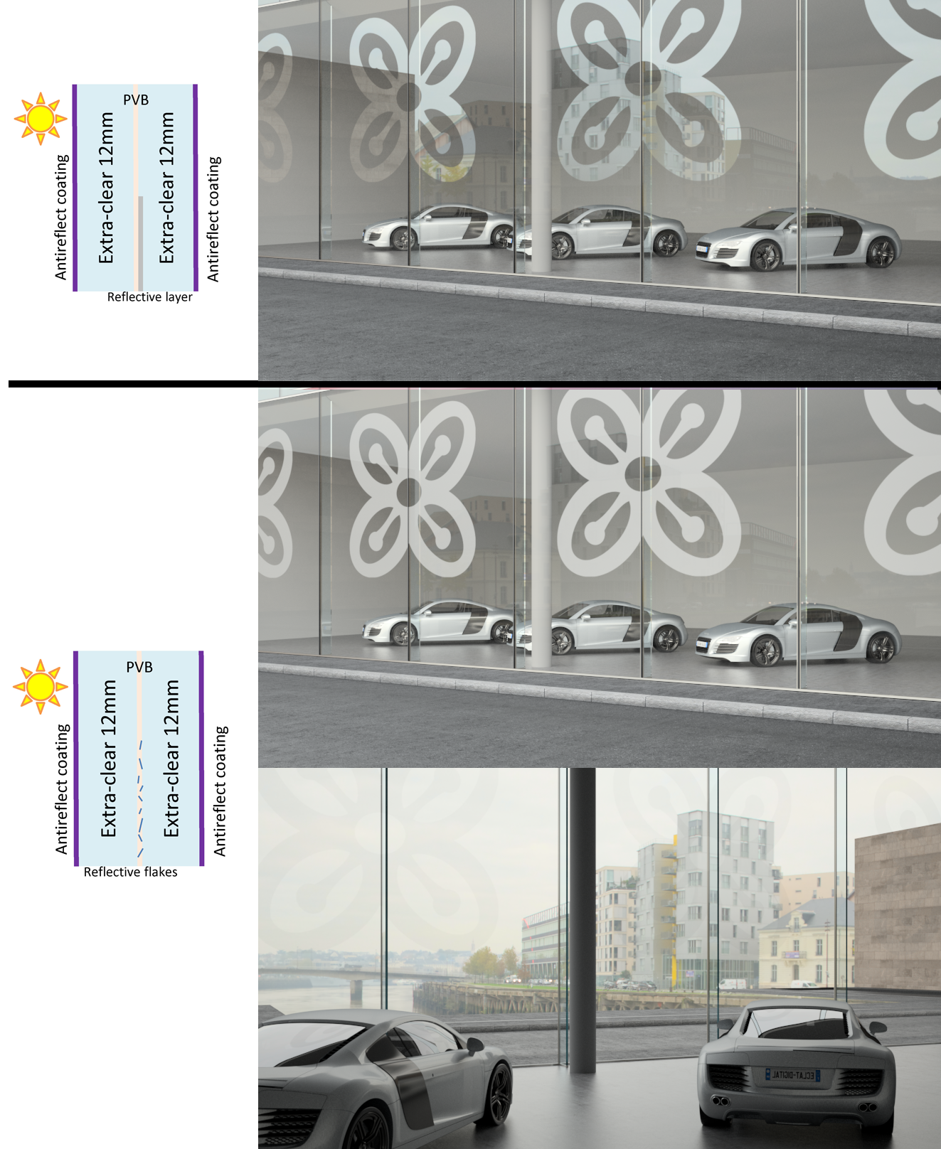
An accurate optical simulation of glazed objects may be used as a powerful design tool. Two glass compositions which integrate a logo in different variations on the theme of transparency are presented below.
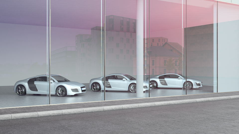
Figure 7 (top) shows a double-sided anti-reflective glass featuring a logo drawn with a reflective coating against the laminate. The reflection only occurs on the logo whereas the rest of the pane has none, letting the graphic stands brightly with a fully transparent glass.
In Figure 7 (bottom) we refer as reflection flakes in the laminate to the superposition of an acid treatment of the whole surface of the second pane upon which the logo area only is coated with a reflective coating. The acid treatment combined with the coating creates a reflective flake effect on the surface, which appears uniform when viewed from a distance of a few meters. The lamination binder fills this roughness and makes it transparent, like a droplet of water onto a translucent shower glass. For the logo area the combination of Acid and reflective coating shows a diffuse reflection from the light side (outside) and fully transparent from the dark side (inside) [6]. Here again translucency is subtle.
Conclusion
In this paper, it was shown that both light simulation algorithms and computing power have reached a level which makes very accurate simulations of glazing possible. This technology can be used as a very powerful tool for visualizing typical glass compositions on projects, but also for designing new compositions, which push the limits of transparency through a subtle and refined use of glass materials.
Acknowledgement
Memorial For Abolition of Slavery Project : Wodiczko + Bonder, Ville de Nantes / Nantes Metropole
References
[1] – M. Radziszewski, K. Boryczko and W. Alda, “An Improved Technique for Full Spectral Rendering,” Journal of WSCG, vol. 17, no. 1-3, pp. 9-16, 2009. [2] – A. Wilkie, R. F. Tobler, C. Ulbricht, G. Zotti and W. Purg, “An Analytical Model for Skylight Polarisation,” in Eurographics Symposium on Rendering, 2004. [3] – T. Hachisuka, “CSE272: Assignment 4,” 26 July 2011. [Online]. Available: http://cs.au.dk/~toshiya/mcp.pdf. [Accessed 3 April 2014]. [4] – E. Veach, Robust Monte Carlo Methods for Light Transport Simulation, PhD dissertation, Stanford University, 1997. [5] – P. Debevec, “Rendering Synthetic Objects into Real Scenes: Bridging Traditional and Image-Based Graphics with Global Illumination and High Dynamic Range Photography,” in SIGGRAPH 98, 1998. [6] – E. Sandré-Chardonnal, “Element transparent à reflexion diffuse”. France Patent WO/2012/104547, 9 August 2012.